Hello
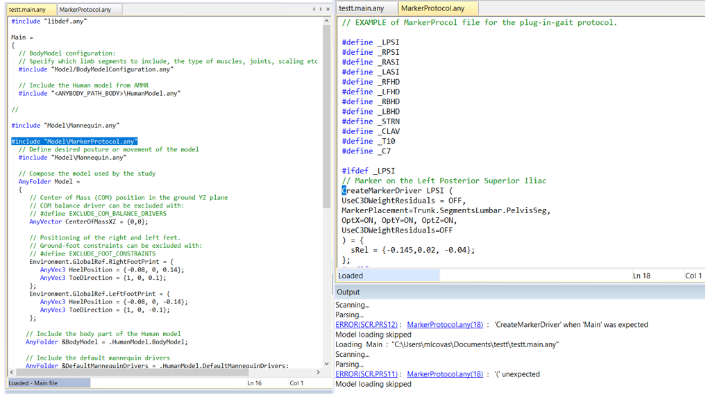
I want to put markers on the standing human model, I am using the marker protocol from Anybody tutorial. I have defined the #include "Model\MarkerProtocol.any" in the Main function, but appears the error "MarkerProtocol.any(18) : '(' unexpected".
The error you see is because CreateMarkerDriver is a class template and its definition must be included in the model.
The mocap model includes all the relevant class templates and framework to work with mocap data (c3d or bvh). Is there any specific reason you want to add markers to the HumanStanding model? What is your goal with this model? If you want to use mocap data to drive your model, then one of the mocap models is a better starting point.
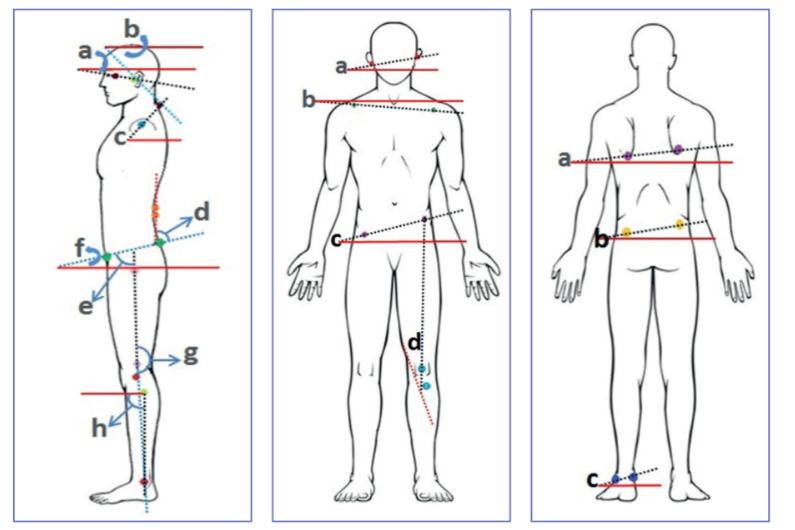
In this case, I don't have X-sens data, which is why I was using a simple model. I want to simulate changes to the hip, shoulder, like in the photo, so I thought that I had to define markers in those areas.
In this case, you can make some reference nodes on the corresponding segments and drive them using some drivers.
There are different types of drivers available in AnyBody. Please select an appropriate one for your use case. Also, please note that if your motion results in an overdeterminate system, you will need to use an overdeterminate solver. Please see this tutorial for more info.
The important concept about where to add new code is that it is included in your study. For this, you need to look at the model tree and be sure which folders are included in the Study. Typically, the folder Model in the model tree will be included in the study.
So when you want to add new segments, please open the scope to Main.Model:
Main.Model = {
  // Add your extra code here
  AnySeg MySeg  = {
  ....
  };
}; // Close Model
Which file exactly you write this code into is less important as long as you include the file in the model. You can of course write it in Model/JointsAndDrivers.any.
Normally, when I make models, I start from one of the standard models and include all of my changes in new files that I can easily include or exclude from the model. I find it easier this way to keep an eye on what all have I changed However, this approach doesn't always work (for example, when I need to change some settings in the existing model and they are defined already somewhere else).
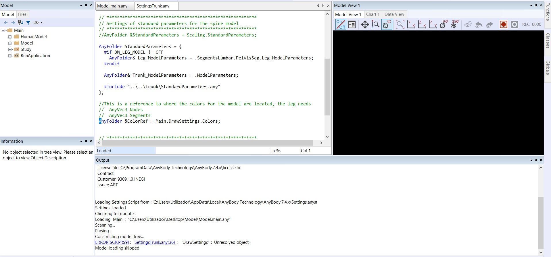
This brings me to your next question. Normally, the folder for Main.DrawSettings is created in our standard models. By default, it is included in the file that loads the HumanModel. Is this one of our standard models? If yes, maybe it's a bug and I would like to know more about it. If not, can you please try:
This statement requires that the path statement ANYBODY_PATH_BODY is defined. If it's not, can you please make sure that the libdef file of your AMMR is included outside of Main = {}; in your main file?
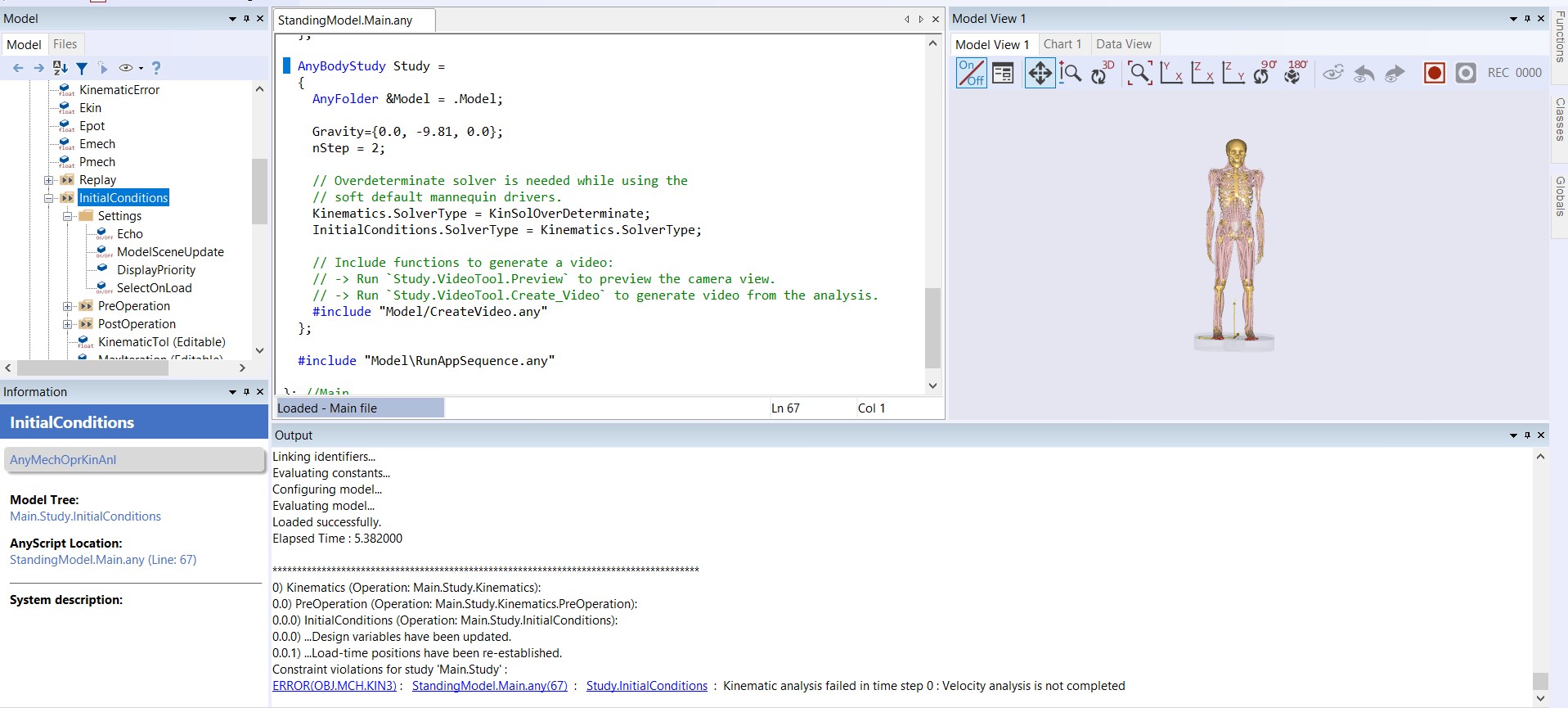
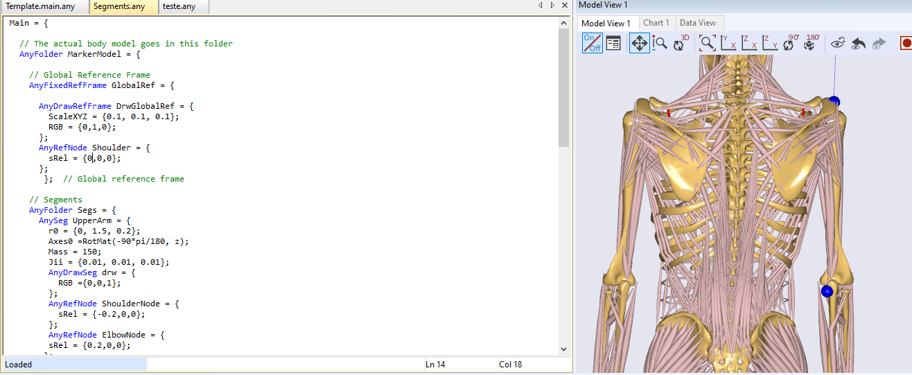
Good afternoon, thank you very much for your help. I'm now clearer about where to add the segments. I was adding the upper arm segment and its reference node. Then I tried to run the model before adding the drivers and I got the following error:
The message says that there is some constraint violation. These kind of messages can be tricky to resolve because the message doesn't specify what is causing the error. I will suggest that you comment out some of the drivers till you are able to run the simulation. Then, you add your drivers one-by-one to see what causes the problem.
I see that you are using an over determinate solver. This means that you have probably added some extra drivers. Have you specified the constraint type for some of these drivers as Soft? You may also want to think about disabling some of the mannikin drivers if you are adding some extra drivers.
Good afternoon, I'm sorry I'm only replying now. I've managed to resolve the error I was getting about the violation of the constriction.
As for the determined solver, it was already defined in the template, do you mean I should comment on that part?
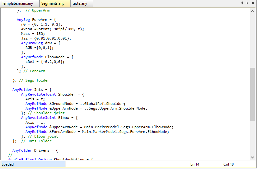
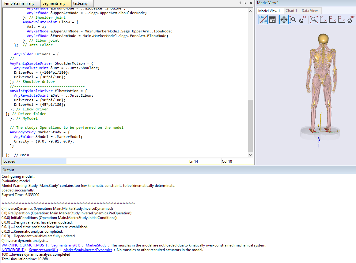
I created the upperarm and forearm segments, with the respective nodes and drivers, but when I ran the inverse dynamics study, the markers were out of place.
I am still struggling to understand how you are trying to drive the model.
You have made new upperarm and forearm segments and then you make a joint of the UpperArm to GlobalRef.Shoulder, which is basically at the Ground. So, when you run this study, you see that these markers are not at the "right" position. But the "right position" must also be defined in the code. The study is doing what it has been told to do.
Also, in the MarkerStudy, it looks like there is no human model included.
If your goal is to drive the human model, you can do so simply through the mannequin file by setting the joint angles and velocities.
Can you please describe what motion you want to prescribe to the human and if you have any input data for this motion?
I suggest you see the following tutorials on how you can specify the human motion:
Good afternoon, thank you very much for your explanation.
I don't have any input data for this model, which is why I chose the Human Standing Model as my template. I wanted to change the markers to simulate the changes at shoulder and hip level, among others, as in the image I sent you a few messages ago. First I was trying to bend the arm by 90 degrees, for example. As I don't have markers at the time, you had told me that to do this I had to create reference nodes in the respective segments and then drive them through the drivers (that's what I was trying to do in the images I sent you). How do I define the position of the reference, through r0? Then I want the mannequin to follow the movement of the markers, I have to connect them through AnyKinEqInterPolDriver, right?
If it's easier, we can arrange a video call to try to clarify this situation.
From the image you shared before, I thought you had some protocol for measuring and specifying movement. This is why I suggested you to create some reference nodes and drive them. Please note that there are different ways to drive a model. You can drive a model without markers as well. You can use AnyKinEqSimpleDriver. The problem with using marker driver is that you don't have any input data, so it is a little bit of an overkill if you have to invent some marker data first and then drive the human model using AnyKinEqInterPolDriver. You can make some reference nodes on the human segments and drive them using AnyKinEqSimpleDriver.
I am sorry I may have misunderstood how you want to drive the model. If you simply want to do some standard joint angle movements, like bending the arm, then using the mannequin drivers is the best approach. The model already has the standard body joint angles that you can control.
We have organized AnyBody Solutions Day on 17th April. Please see this link and feel free to book a slot.
Thank you very much for the explanation and for sharing AnyBody Solutions Day. No problem, don't worry, sometimes it's not easy to explain your doubts in writing