I did that and I had also to delete some markers In the C3D input file as it was hidden from the camera for some time intervals in the recording and I had to deactivate them in AnyBody as well (e.g.: LASI)..
AnyBody can handle marker drop-outs. If you MoCap system has registered the dropout periods correctly in the C3D file, then the Marker class-template in AnyBody will set the markers weights to zero when the marker drops out.
However, letting AnyBody handle the marker dropouts should be the last resort. You should clean up your MoCap data in your MoCap recording software. Like gap-filling small drop-outs and cutting the the recording so the first frame doesn't contain any dropouts.
Otherwise, it will be more painfull to work with the data afterwards.
Actually using 40 markers as an input gave over-defined issues to loading the model at the initial frame properly, some markers had to be deactivated especially on the pelvis like RASI.
With many markers you should think a lot about which marker positions are optimized in the Parameter identification step. Only the markers on bony landmarks should be fixed relative to the model. The remaining markers positions should be "free" to be optimized.
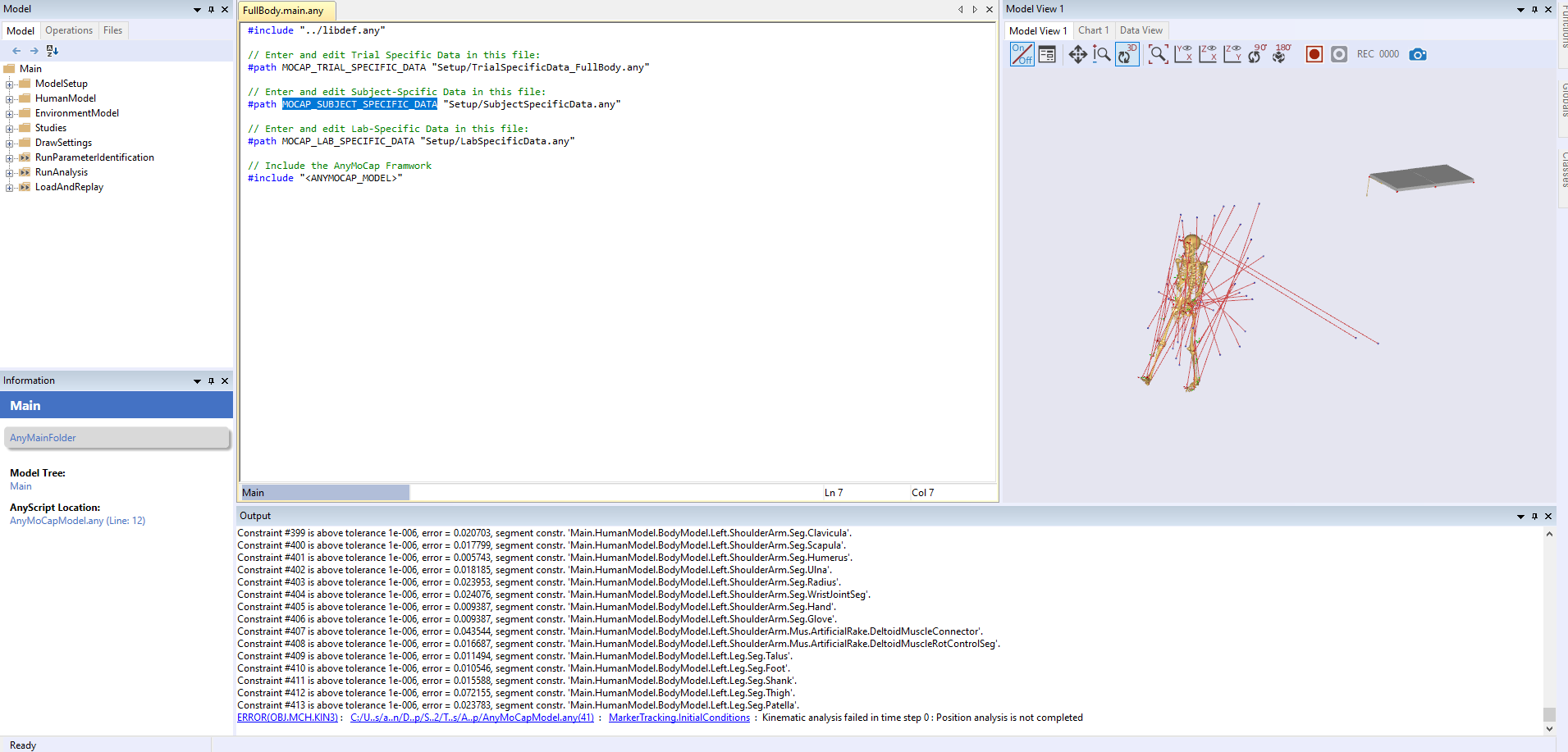
The analysis managed to start but there were some warnings or errors like:
-Warning: overloaded muscle configuration (this even appeared in the gait analysis!!)
-Error: latissimus_dorsi_5.SPLine : Number of allowed iterations for contact solution has been exceeded
Concerning the overloaded muscle configuration error, does this warning affect the overall results obtained from the inverse dynamics? and why did it appear even in gait analysis?!
I should probably see your model before I can really advice you here.
There are many possible causes. I have seen many cases where the gravity vector was not downwards, or cases where noise in the input data caused high frequency accelerations which the muscles could not provide enough force to balance. But it could be a whole lot of other things.
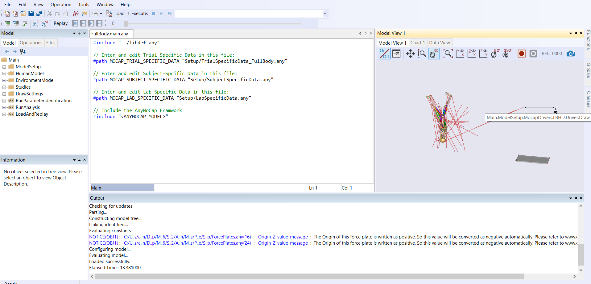
-Why the RBAK appears in the drivers' list but it doesn't appear in the defined markers?!
The entries in Main.ModelSetup.C3DFileData.Points.Markers are just loaded data from the C3D file.
So if there is a RBAK marker in the c3d file, you will also find it here. That doesn't mean that the marker is used in the model. In the file Setup/MarkerProtocol.any are the code that create the markers. Here you see entries like
CreateMarkerDriver RPSI (
MarkerName= RPSI,
MarkerPlacement=Trunk.Segments.PelvisSeg,
OptX=OFF, OptY=OFF, OptZ=ON,
UseC3DWeightResiduals=ON
) = {
  sRelOpt = {-0.145,0.02, 0.04};
};
The CreateMarkerDriver is the name of class-template. It expands to a lot of anyscript code that ands the necessary connetions between the data in the c3d file and the model. If you have the newest version of AnyBody then try to right-click the CreateMarkerDriver name and select "Go to Class Template". Then you can see all the anyscript code it creates.
If you have more markers in your C3D file which are not in the example you started with, then you need to add them your self in MarkerProtocol.any file.
-What is the maximum accepted distance between the force plate and the model feet to initiate the kinematics successfully?
The force-plate is only used to apply external forces to the model when you run the "inverse dynamics" simulation. So it has no influence on the kinematics. But the code is constructed in such as way that the forces are only applied to the foot if the foot is close to the plate and moves with a speed below a certain threshold.
Force plates are also implemented with "class-template" to make the easier to add. The class templates have few arguments: (HeightTolerance and VelThreshold), which control this. See Setup/ForcePlates.any in your example.
-The drivers of the markers usually load following the initial frame in the C3D file, while the markers load only following the model posture defined in PelvisPos, correct?..
I don't understand what you mean here. I guess my initial answer is no - that is not how it works.
I would really recommend that you try the tutorial:
Making things move — AnyBody Tutorials v7.4.0-dev (anyscript.org)
You shouldn't spend too much time on tutorials, but I think this one will help clarify some the concepts.
Does this mean the smaller the gap between the drivers and their linked markers the better to kick off the kinematics analysis successfully?
That is generally correct. It is an optimization problem so a better start guess is always better. But it is generally only an issue for the solver if the model loads upside down or faces the wrong way.
-Why when using force plate offset, the corners don't move with the force plate despite its coordinates changing already according to the offset?
That is true. The corners are a property of the force plate definition in the C3D file. So they remain where the are. What you move is the area where contact with the plate is detected, and the surface on which center of pressure is calculated. So it is important that the offset correspond with the actual object that was connected or mounted on top of the force plate.
in the case of sitdown or standup movement, the hip joint contact forces should be similar as long as the recorded movement was for a subject exerting force on the force plate in a similar posture left/right side of the body. Correct?
I guess so, but I am not sure I totally understand your question. If the motion and forces are complelty symmetric then the forces will be the same on both side.
What if hip joints' contact forces come out different from the inverse dynamics analysis?! the MS model should be identical compared to a human body which has individual asymmetric nature.
If you are simulating some one with different leg length then you should scale your model accordingly. By default the model is setup expect equal leg length. But it doesn't have to be this way. The model is normally scaled from the markers. But I would question if you could detect small differences in leg length based on markers. The uncertainties in placing makers on the subject are usually larger.
Another question, if the force plate records a single value of forces reaction, how it could differentiate which leg is exerting a higher load on the force plate compared to the other one? this is identified from the moments as I understand? correct?
That is a good question. It is of course best to have two force plates. With a foot on each. But AnyBody can work with both feet on the same platform. (You must allow this explicitly in the force plate class by setting the variable ALLOW_MULTI_LIMB_CONTACT see ForcePlates.any).
In this case the single external force will be distributed between the feet in such a way to best balance gravity. It automatically comes as a consequence of the muscle recruitment algorithm which minimizes the muscle activation.