Change treadmill tilt

Hello,

I measured subjects walking on an inclined and declined (+/-4°) dual belt treadmill with force plates integrated in the treadmill (GRAIL, Motek Medical B.V., Houten, Netherlands). The system was calibrated with the treadmill in an even position.
I’m using the Plug-in-gait_Simple LowerExtremity model from the MocapExamples in AMMR 2.3.1. Is it possible to add an incline to the treadmill in this model? I tried to run the analysis with following force plate settings:

Main.EnvironmentModel.ForcePlates =
{

ForcePlateAutoDetection Plate1(
PLATE_NO=1,
HeightTolerance = 0.07,
VelThreshold = 2.2,
FORCEPLATE_TYPE = 2,
ALLOW_MULTI_LIMB_CONTACT = OFF
) = { GroundVelocity = {0,0.9,0};
};

ForcePlateAutoDetection Plate2(
PLATE_NO=2,
HeightTolerance = 0.07,
VelThreshold = 2.2,
FORCEPLATE_TYPE = 2,
ALLOW_MULTI_LIMB_CONTACT = OFF
) = { GroundVelocity = {0,0.9,0};
};
};

This works for the even position but not for an inclined/declined treadmill, as shown below.

image

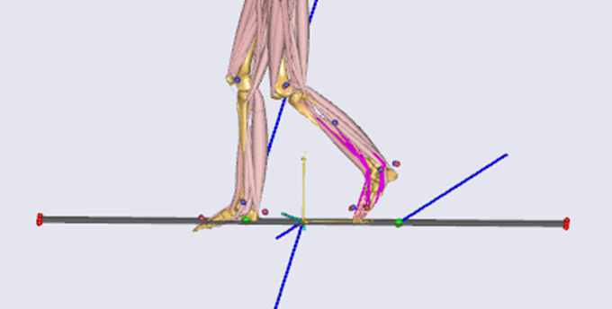
Is it possible to change the force plate settings according to the incline within the model? I’ve read the post “MoCap on a ramped treadmill” but was wondering if any other solution was found since 2022.
Thank you in advance for any insights or suggestions!

Dear Judith,

Welcome to the AnyScript forum!

I have not checked specifically for AMMR 2.3.1, and I would encourage you to update to the newest version of the AMMR and AMS as it's around 4 years old now.

Nonetheless, I think you should be able to adjust the corners through the ForcePlateAutoDetection class template. You can override the corners of the forceplates specified in the c3d file. Try these lines:

Main.EnvironmentModel.ForcePlates =
{

ForcePlateAutoDetection Plate1(
PLATE_NO=1,
HeightTolerance = 0.07,
VelThreshold = 2.2,
FORCEPLATE_TYPE = 2,
ALLOW_MULTI_LIMB_CONTACT = OFF
) = { GroundVelocity = {0,0.9,0};
   ForcePlateInfo.CORNERS = {{{493.65, -22.719, -447.433}, {492.871, -23.7673, 4.51691}, {-6.18936, -24.9433, 2.48103}, {-4.46875, -23.4108, -449.314}},
                              {{1256.41, -13.532, -679.267}, {1252.38, -14.1924, -229.51}, {758.888, -20.2354, -231.383}, {758.717, -20.3881, -681.816}}};
};

ForcePlateAutoDetection Plate2(
PLATE_NO=2,
HeightTolerance = 0.07,
VelThreshold = 2.2,
FORCEPLATE_TYPE = 2,
ALLOW_MULTI_LIMB_CONTACT = OFF
) = { GroundVelocity = {0,0.9,0};
ForcePlateInfo.CORNERS = {{{493.65, -22.719, -447.433}, {492.871, -23.7673, 4.51691}, {-6.18936, -24.9433, 2.48103}, {-4.46875, -23.4108, -449.314}},
                              {{1256.41, -13.532, -679.267}, {1252.38, -14.1924, -229.51}, {758.888, -20.2354, -231.383}, {758.717, -20.3881, -681.816}}};
};
};

The corners above are just an example from the Plug-in Gait simple model, so you must adjust them for your model. You should firstly look at the values of the Corners in your c3d file so you know what units they are defined in. Then, try to update the corners in a consistent way, that is, have the same units and same sequence of corners. You can also try to use some trigonometric functions in AnyBody to make a relation of the corners with the inclination angle. Please note that you have to specify the corners of all the force plates when you modify this argument as it must match the expected dimension of the variable.

One last thing, I am still in doubt about how the force plate calibration might affect the results if you manually adjust the corners like this to introduce the incline. The force values must be saved in the c3d file with some assumption and calibration, and this will adjust a part of that assumption. Please check if your results are sensible.

Best regards,
Dave