Hi
I input C3D file to anybody i change name of marker and type of forceplate. but when i save and load ,i can’t see the forceplate and line of all markers connect to origin(0,0,0)(blue markers).
I try to check the SRel each a marker , input to new file and search the github but i can’t to slove this problem. I don’t understand that where’s mistake. Even if ,a past file i do same with this file but it s successly.
i can’t attach file zip but i attach my pic.
Thank you
Have you checked the units? It looks like your markers on the model relate to something much smaller because all red lines concentrate in one point.
Hi,Søren,
I was using the GM-foot model.As you mentioned,the plantar pressure mat is needed for distributing the ground reaction force.However,the pressure pat is not available for me.I was wondering if I could use the pressure insoles to distribute the ground reaction force instead of using the pressure mat?
Best regards,
Johntiger
Hi Soren and John,
I hope you don’t mind the contribution of my thoughts. I think to get this to work you would need to convert the insole pressure data output from the software you are using to a text file and then format that to match the current repository text file.
Hi Zach,
Thanks very much for your message.
It sounds reasonable but a little challenging, but I will have a try and modify the insole pressure data to match the current txt file.
Best regards,
John
Hi John,
I think there are two ways:
[ol]
[li] do as Zach describes convert your data to the pressure plate format, i guess it is possible but it may not be very elegant, in this way you may avoid to change the python code which read the data.
[/li][li] make a new script that applies the load to the foot, using your data. You will need to read the data in using an AnyInputFile then apply the loads to the specific nodes on the foot corresponding to your data, give the force a direction using the forceplate data, possibly also scale the pressure data using the forceplate data, since it is likely to have a more accurate net force.
[/li][/ol]
Best regards
Søren
Hi Søren,
Thanks very much for your suggestion.
I will have a try with the methods you suggested.
Best regards,
John
Hi Søren,
I’m sorry to disturb you again.
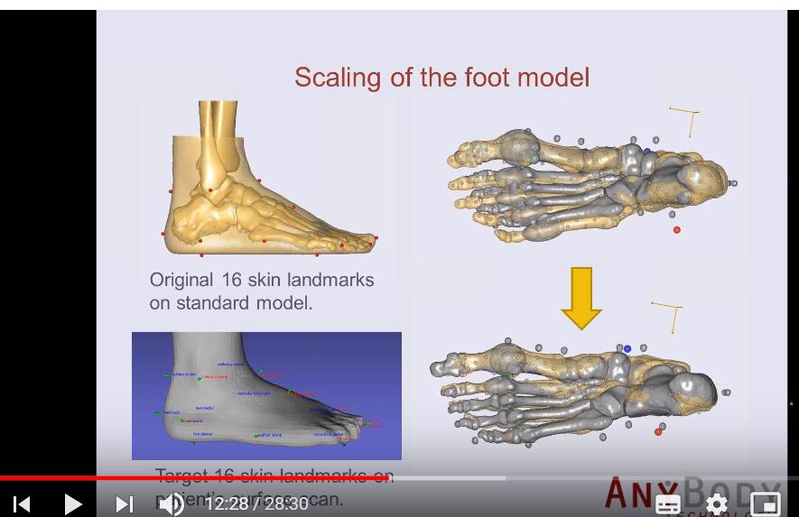
I was wondering if I could get the foot skin geometry (stl format) of the GM-foot model from you. I observed the there is a skin geometry (stl) file in the video :Scaling of the AnyBody GlasgowMaastricht Foot Model in MeshLab ( https://www.youtube.com/watch?v=BmB-88o8uYY&feature=youtu.be).
Thanks for your work.
Best regards,
John
Hi John
I have added the skin to the GM foot model we have available here:
Best regards
Søren
Dear Søren,
Thanks very much for your work!
I will check the stl file.
Best regards,
John
Dear Søren,
I am sorry to disturb you again. The FootGMSkin.stl you upload is target skin. I noticed that there is an original foot skin for the GM-foot model. https://www.youtube.com/watch?v=8nTeU621hhA. I was wondering if you could upload the original skin for the GM-foot model. I hope I could improve the scaling process based on the original skin automatically instead of manually selecting the paired points.
Thanks for your work.I am looking forward to your reply!
Best regards,
John
Hi John,
I have checked again, this file is the one from the original foot skin, not a target.
I think the registration might be different from the bones though.
Best regards
Søren
Hi Søren,
Thanks much for your reply!
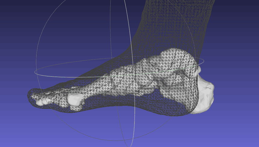
I have uploaded two pics about the foot model. In the second picture, I noticed the standard bone and original skin could be assembled together.
I also hope to assemble bone and foot skin geometries. And I have exported the bone geometries from FreePostureFootGMFoot model and try to assemble the bone and skin together. However, foot bone is longer when compared with the foot skin,seen in the first picture. Could you please provide me some suggestions? Or if you could provide the assembled bone and skin geometries?
Thanks very much for your patience and work!
Best regards,
John
Hi John,
The only thing i could see go wrong would be if scaling was applied when you did the export or if you have scaled the skin.
I have tested again using the FreePostureGMFootModel for export and the bones do fit inside.
Maybe you have changed the FreePostureModel so that foot bones are being scaled this could explain it.
You could make a model which did nothing but including the bones and then try to export calcaneous and distalphalangeal1 and see if they fits inside skin.
Best regards
Søren
Hi Søren,
Thanks very much for your suggestions!
I used the original geometries and remove scaling . Then the bones could fit inside the skin.
I really appreciate your help!
Best regards,
John
This topic was automatically closed 125 days after the last reply. New replies are no longer allowed.