We are currently working on personalization based on medical images. When using the Any tutorials (15: Personalizing your model) there was the problem that the tutorials work with the older TLEM leg model, but the scripts of the 7.3 AMS/2.3 AMMR version use TLEM2.
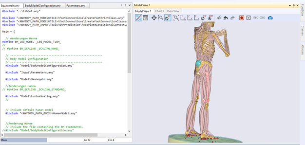
So we used #define BM_LEG_MODEL LEG_MODEL_TLEM in the standing model. So the custom scaling worked well. Now we want to transfer the custom scaling to the squad model and use TLEM2.
We have already been advised to do so:
#define BM_SCALING SCALING_NONE
double-clicking on the right femur bone, navigating to the Model Tree, right-clicking on the surface object and exporting the surface using 'Export Surface' function (scale factor of 1.0, local ref. frame).
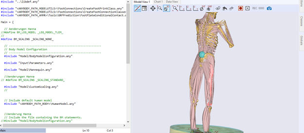
However, with the TLEM2 model the femur seems too long and curved to us.
TLEM 1:
Did you change the source landmarks to correspond to the TLEM2.0 surfaces? Typically the problem is in inconsistency of the input data, that leads to a some sort of extrapolation. As soon as you have all source entities (underlying model, landmarks, surfaces) matching and target entities matching too - everything just works.
Where do I find the source entities? And how can I change them?
We used the source entities from the tutorial "Personalizing Your Model". Is it possible to change them? If so, how do I have to do that?
In this tutorial: SourceFemur.stl is the source bone to be replaced with TLEM2.0 version of it; Points0 is the matrix (or matrices) of landmarks on the source surface that needs to be replaced with the matrix describing same landmarks on the TLEM2.0 surface. You can use Meshlab software for picking points or anything else that allows for 3D point picking.
Hello again,
we are still in the process of personalizing our model, but we only want to individualize the knees.
New questions have arisen:
We have already segmented the knees and provided them as STL files and now we want to read out coordinates in CATIA (not Meshlab). Is that possible? What do we have to make sure that it fits the unit of AnyBody?
And how do I find out how the corresponding points, whose coordinates I need, are defined? For example, where is the lateral anterior condyle or the lateral posterior condyle?
We are looking forward to your tips and help.
Thank you.
You can pick points in any software of choice, but for the purpose of modeling in AnyBody you would need to write a matrix containing coordinates like shown in the tutorials:
Reading a MeshLab generated landmarks file (.pp, picked points) can be automated, but if automation is not a problem - you can just write such matrix manually or convert CATIA-produced coordinate text file into AnyScript.
Regarding what landmarks to choose - it depends on your purpose, if you only want to visualize (meaning that there is not scaling of the model), you can select 4 or more points that represents distinct landmarks and easily distinguishable on both, source (AnyBody) and target (CT), surfaces. This allows to create a rigid body or uniform scaling registration transformation that can be used to align bones.
If you want real scaling and happy with a simple uniform scaling - i would probably try selecting "corners" as landmarks to capture the size of the bone in the best possible way. Effectively you want to deform the source bone to the target shape - it is just an interpolation where you pull and push surface to match the needed shape, in a way.
If you already have source landmarks - visualize them against source surface and try finding corresponding points on the target surface. Typically these are prominent peaks and, say, tips of bony processes. For typical application, you can guide yourself visually.
AnyBody units are meters. CT scans typically come in mm - use a multiplier of 0.001 to convert your surfaces/landmarks.
Hello Pavel,
thanks for the last answer. It was very helpful and a lot has happened in the meantime.
I glued my part of the femur to the SourceFemur from the tutorial and then selected some landmarks and read out their coordinates.
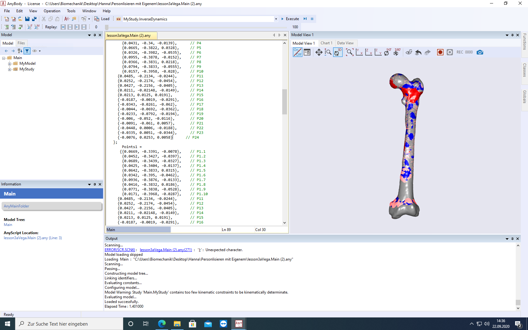
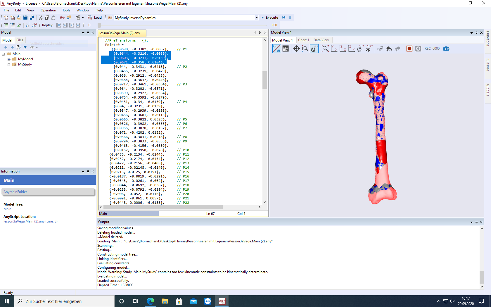
Now I have done the steps as in the tutorial "Personalizing Your Model" Lesson1 and get a picture like this:
The selected pink area corresponds to my part of the femur. However, the transition to the shaft and the size of the condyles are not correct because my TargetFemur is actually smaller here.
It seems to me that despite my input and the desired transformation of the SourceFemur into the TargetFemur, the TargetFemur is always overlaid by the SourceFemur.
What can I do to finally get to my TargetFemur?
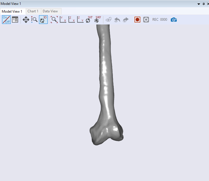
The TargetFemur should look like this in the area of the condyles:
I think you did everything well, except the distal part. In order to capture those features like the thinner piece - you need to add some control landmarks. What we construct is an interpolation/extrapolation transformations, which only knows the behavior from control points. Try adding a point in the region of interest.
Secondly, you can replace the bone surface for visual purpose, but the morphing actually deforms AnyBody bone with all muscle attachments to take a target's shape. If you do a rough scaling and don't mind minor inaccuracies in terms of muscle attachments. You can hide the bone and draw your own (but it has to align with the target bone, you can use the reverse transformation to put it where is needed).
Main.HumanModel.BodyModel.Right.Leg.Seg.Thigh.Drw3.Visible = Off; // Hides the bone
AnyDrawSurf - read the ref. manual and search for examples how to use it to draw your own (remember scaling factor to convert from mm to m).
Hello Pavel,
thanks for your answer.
I have added control landmarks (e.g. the ones highlighted in blue in the script) - as you recommended - to capture the thinner piece at the distal end.
However, unfortunately this did not change anything.
The pink areas are always those of the source femur.
I did morphing for mandible before and the result were amazing. It just needs patience and try and error.
I Chose 3d position of landmarks by Solidworks. It is a completely approximately process and there is no rule about the exact position of each Landmark on your target bone. The most important thing is to choose corresponding landmarks correctly on the target and the source bones.
One suggestion is that after each try (morphing process), export the morphed bone from AnyBody and open both target and morphed bone in a software like Geomagic and perform a deviation analysis. where the deviation is relatively high, you can add new landmarks.
Can I ask which functions (e.g. AnyFunTransform3DLin2,...?) do you use in AnyBody for scaling and morphing?
Hi Iman,
I have done the steps as in the tutorial "Personalizing Your Model" Lesson 1 and therefore used the following functions for scaling and morphing:
AnyFunTransform3DLin2
AnyFunTransform3DRBF
AnyFunTransform3DSTL.
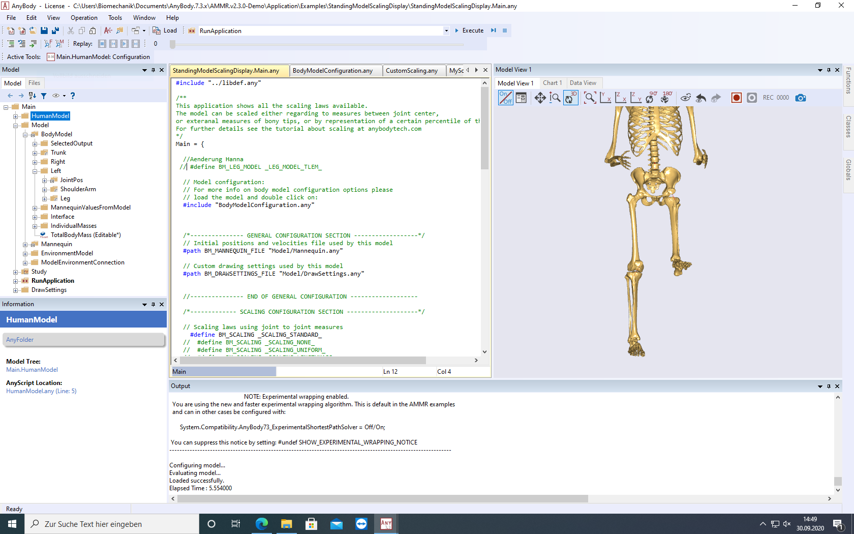
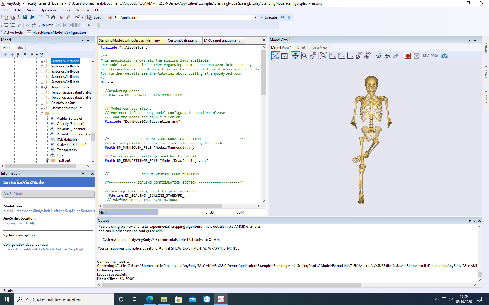
now I have taken another step forward and tried to integrate my femur into the StandingModelScalingDisplay like in the tutorial "Personalizing Your Model" Lesson 2.
I think that my scaling and morphing now fits quite well.
But when I now try to include it into the model, it looks like this:
How can I replace the SourceFemur.stl with the TLEM2.0 version of it?
Where can I find the source-bones (TLEM2.0) as STL files?
I also need them to find my coordinates at the landmarks.
Is it possible to download the femur, tibia and patella from the right and left side as STL files?
I am very happy about an answer!
Best regards
Hanna
You can then export bones as STL by double-clicking on the bone, navigating to Model Tree and right-clicking on the drawing object for export. Choose Export Surface -> choose location -> Scaling Factor of 1.0 -> Local Reference Frame.
You can export the left side too, but as shown in tutorials it is enough to have the right side surfaces (and the code is ready for that).
Hello Pavel,
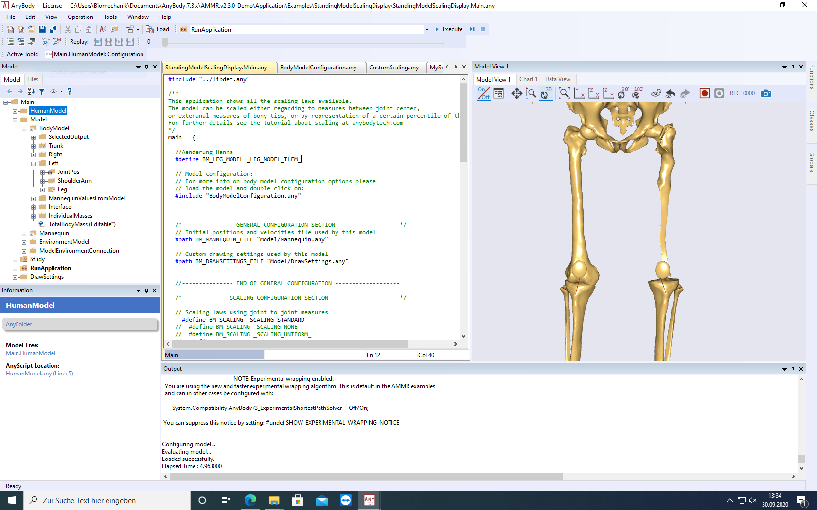
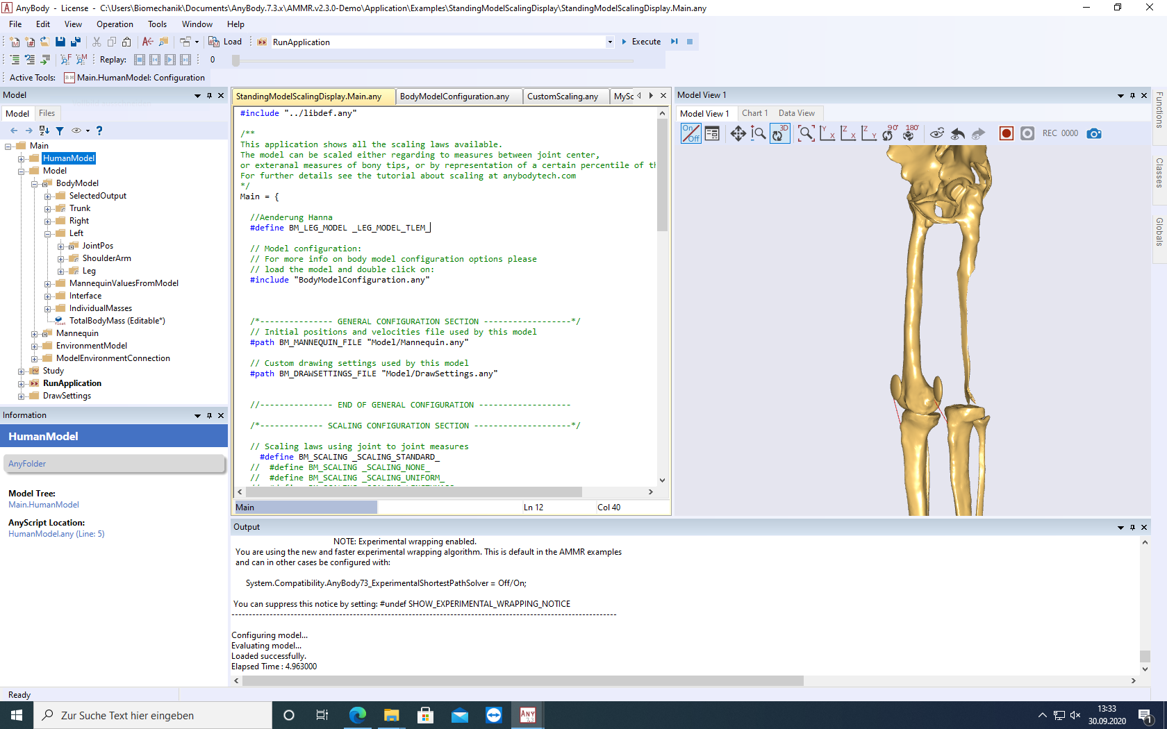
I have done and carried out everything as described by you. I loaded the new version and TLEM2 and then exported the left femur (as recommended in your last post).
Then I picked out new landmarks and entered them into AnyBody.
Now when I load the model it looks like this:
Something is not matching - most likely the landmarks do not correspond to the source geometry used in the generic model, could still be TLEM1 vs TLEM2 problem.
Unfortunately i cannot help more than this without knowing how you do it.