I use AnyInputC3D function to load c3d data. But the analog data are all larger than their real value. For example, the F1Z is 900 in anybody model while the real value is 530 in c3d file.
I am not sure the reason.
Hi @kkzh2008
I dont have a lot to go on from your question, but try and have a look on our Wiki page regarding the use of MoCap data. Here you can get help to troubleshoot the most common errors when importing c3d data.
Best Regards,
Bjørn
AnyBody Technology
We used AMTI force plate, and the code in forceplate.any as follow:
ForcePlateType4AutoDetection Plate1 (
PlateName = Plate1,
Folder =Main.ModelSetup.C3DFileData,
Limb1= .BodyModelRef.Right.Leg.Seg.Foot,
Limb2= .BodyModelRef.Left.Leg.Seg.Foot,
No=0,
VerticalDirection ="Y",
HeightTolerance=0.07,
VelThreshold=2.2,
Fx=Main.ModelSetup.C3DFileData.Analog.DataFiltered.F1X,
Fy=Main.ModelSetup.C3DFileData.Analog.DataFiltered.F1Y,
Fz=Main.ModelSetup.C3DFileData.Analog.DataFiltered.F1Z,
Mx=Main.ModelSetup.C3DFileData.Analog.DataFiltered.M1X,
My=Main.ModelSetup.C3DFileData.Analog.DataFiltered.M1Y,
Mz=Main.ModelSetup.C3DFileData.Analog.DataFiltered.M1Z,
FootPresent=HumanModelPresent)
={
Cal=Main.ModelSetup.C3DFileData.Groups.FORCE_PLATFORM.CAL_MATRIX.Data[0];
Switch_DrawForceVectorFromCOP = On;
};
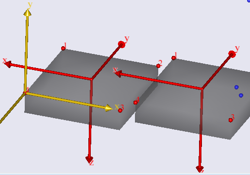
The coordination of the force plate and global coordination were shown in the following figure.
|Real F1X= -0.523|-0.392|-0.698|-0.785|-0.261|
|Anybody load F1X= -3.662 |-2.746|-4.882|-5.493|-1.831|
| Ratio= 0.143|0.143|0.143|0.143|0.143|
|Real F1Y= -0.545|-0.098|-0.141|-1.003|-0.403|
|Anybody load F1Y= -3.814|-0.686|-0.991|-7.019|-2.822|
| Ratio= 0.571|0.571|0.571|0.571|0.571|
|Real F1Z= -0.392|-0.914|-0.479|0.914|-1.481
|Anybody load F1Z= -0.686|-1.602|-0.839|1.602|-2.593
| Ratio=0.143|0.143|0.143|0.143|0.143|
|Real M1X= 211|258|187|211|211
|Anybody load M1X= 2.7|3.3|2.4|2.7|2.7
| Ratio= 77|77|77|77|77
|Real M1Y=144|-216|-90|72 |108
|Anybody load M1Y= 2.4|-3.6|-1.5|1.2 |1.8
| Ratio= 59|59 |59| 59|59
|Real M1Z=54|208|54|197|98
|Anybody load M1Z= 1.5|5.7|1.5|5.4|2.7
| Ratio=36|36|36|36|36
Hi @kkzh2008
Have you checked your vertical direction and calibration matrixes for the plates?
The reference frames in the photo seems a bit strange?
If that does not work, you can send me a working copy of your model and i will try and have a closer look
Best Regards
Bjørn
I have tried to change the vertical direction. However,It did not work.
I am not sure how to check the calibration matrixes. Is there any tutorial?
The following file is my c3d file. I have tried to use the demo file (AnyInputC3D.zip) to load my c3d file. However, the GRF data is also wrong.
123.zip (52.1 KB)
Hi Kaison,
I have looked at the calibration data in the C3D file, it seem not to match the description you made in a previous post.
You can see the values here in the C3D object once you have loaded the model. "....Groups.FORCE_PLATFORM.CAL_MATRIX.Data"
{
{
{0.143, 0.0, 0.0, 0.0, 0.0, 0.0},
{0.0, 0.143, 0.0, 0.0, 0.0, 0.0},
{0.0, 0.0, 0.571, 0.0, 0.0, 0.0},
{0.0, 0.0, 0.0, 77.0, 0.0, 0.0},
{0.0, 0.0, 0.0, 0.0, 59.0, 0.0},
{0.0, 0.0, 0.0, 0.0, 0.0, 36.0}},......
}
Note that here y and z factors are swapped compare to what you wrote above, so to me it looks like the calibration matrix has not been saved correctly into the c3d file.
To fix it either create a new c3d file or construct a correct calibration matrix usinfg an AnyFloat in AnyBody and then use this new matrix to be applied in the forceplate.
Best regards
Søren
Hi Søren
Thanks for your response, How could I get the right calibration matrix?
Thanks
Best Regards
Hi Kaison,
If you can not export the correct matrix from the software which creates the C3D file you can create an alternative manually in AnyBody.
So in this case it would be
AnyFloat MyCorrectedCalMatrix1 ={
{0.143, 0.0, 0.0, 0.0, 0.0, 0.0},
{0.0, 0.571 , 0.0, 0.0, 0.0, 0.0},
{0.0, 0.0, 0.143, 0.0, 0.0, 0.0},
{0.0, 0.0, 0.0, 77.0, 0.0, 0.0},
{0.0, 0.0, 0.0, 0.0, 59.0, 0.0},
{0.0, 0.0, 0.0, 0.0, 0.0, 36.0}};
Then when defining the force plate you would point at this object instead of the calibration matrix from C3D file.
You would do something similar for the other plate, if needed.
Best regards
Søren
This topic was automatically closed 125 days after the last reply. New replies are no longer allowed.