Defining a moving ref frame directly from c3d marker position data

Hello,
I've adapted the multi trial Mocap model for a cycling session. I have force data from the pedal and 2 markers (called RPED and RPEP) in the c3d file that define the plane of the pedal.
I would like to manually define a moving reference frame inside the foot instantaneously consistent with the pedal orientation, exploiting the position data of the pedal markers that are stored under Main.ModelSetup.C3DFileData.Points.Markers.RPED.PosInterpol.Data (which is a 900x3 AnyMatrix, 900 being the number of frames) without creating new marker drivers, such that I can use this ref node as point of attack of the force data.

This is how it currently looks like:

AnyRefNode PedalRight = {
AnyVec3 O = 0.5*(Main.HumanModel.BodyModel.Right.Leg.Seg.Foot.RTVM.sRel + Main.HumanModel.BodyModel.Right.Leg.Seg.Foot.RTFB.sRel);
AnyVec3 X = ?
AnyVec3 Y = {0.0,1.0,0.0};
AnyVec3 Z = cross(X,Y);
sRel = O;
ARel = {X/vnorm(X),Y/vnorm(Y),Z/vnorm(Z)}';
};

For X, I want to exploit the difference of the 2 position vectors, i.e. for the n-th frame taking the the n-th component of the difference of the Pos matrices of the 2 markers.
Is there a way to do this or should I consider other approaches?

Best regards,
Marco

Hi @MDrago and welcome to the forum!

I'm not entirely sure I understand what you try to accomplish.
You have marker data for the pedal? Is it only the orientation or is it the displacement? or both?

If you want to drive the position and orientation of the pedal node you can use a AnyKinMarkerDriver
There is a pretty good example in this tutorial that can help you set up the driver and point the correct marker data to it.

There is also this tutorial on how to setup external forces to be dependent on time and read from a file. Maybe that can help.

Best regards,
Bjørn

Hi Bjorn,
thank you for the reply!
Let me explain the problem better.

I have pedal markers trajectory data from the c3d file, but I did not model (nor I'd like to) the pedal itself, so I don't have pedal nodes defined in a "pedal segment" that I can drive.

I'd like to apply force data, coming from the instrumented pedal, directly to the foot, but in a reference frame consistent with the pedal, because the force components data are parallel and perpendicular to the pedal.

To do this, I have already set up a loads folder with interpolated time-varying forces, but as first attempt I applied the force to a forefoot marker (RTTO), and the simulation worked nice:

AnyForce3D FRight = {
AnyRefFrame &PointofAttack = Main.HumanModel.BodyModel.Right.Leg.Seg.Foot.RTTO;

    AnyFunInterpol Forcex = {
      Type = PiecewiseLinear;
      FileName = "FxR.txt";
    };        
    AnyFunInterpol Forcez = {
      Type = PiecewiseLinear;
      FileName = "FzR.txt";
    };        

    AnyVector Fx = Forcex(t);
    AnyVector Fz = Forcez(t);
    
    Flocal = {Fx[0],0,Fz[0]}; 
  };

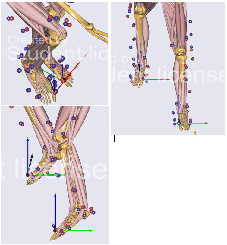
However, the RTTO reference frame is not exactly aligned with the pedal reference frame, so the force input is not interpreted in the right way, because the foot moves with respect to the pedal over time.

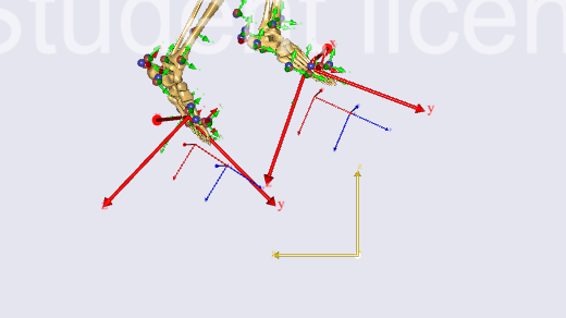
Therefore, I would now like to define a new reference frame, inside the foot, but with axes oriented as the pedal, i.e. oriented as the vector that connects the 2 pedal markers over time.
The reference frame should have its origin in the middle of the forefoot (point O below).

I've tried to use the same approach used for the time-dependent force to handle the manual definition of the moving reference frame:

Main.HumanModel.BodyModel.Right.Leg.Seg.Foot = {

 AnyRefNode PedalFrame = 
    {
    AnyVec3 O = 0.5*(Main.HumanModel.BodyModel.Right.Leg.Seg.Foot.RTVM.sRel + 
                                  Main.HumanModel.BodyModel.Right.Leg.Seg.Foot.RTFB.sRel);

    AnyFunInterpol &RPED = Main.ModelSetup.C3DFileData.Points.Markers.RPED.PosInterpol;
    AnyFunInterpol &RPEP = Main.ModelSetup.C3DFileData.Points.Markers.RPEP.PosInterpol;
    AnyVec3 X = RPED(t) - RPEP(t);
    AnyVec3 Y =  {0.0,0.0,1.0};
    AnyVec3 Z = cross(X,Y);
    sRel = O;
    ARel = {X/vnorm(X),Y/vnorm(Y),Z/vnorm(Z)}';
    };         

};

but I got this error:
ERROR(SCR.EXP10) Expression evaluation failed at moment 'DesignVar':
X: argument will not be ready for evaluation until moment 'TimeVar'

Ideally I wouldn't like to create marker drivers for the pedal markers, also because as already mentioned I don't have a pedal segment.

I hope the problem is now clearer.

Best regards,
Marco

This is how the RTTO ref frame looks like. The red axis is fine, but I would like the green and blue axes to be respectively parallel and perpendicular to the pedal. So the new ref frame should have the green axis with the same orientation of the vector that connects the 2 pedal markers (not displayed in the pictures), the red axis staying the same and the blue one being the cross product of the two. Also, the point of application should be approximately at the center of the forefoot.

Hi @MDrago

Thanks for the explanation that helps a lot.

What you are trying to do is not possible with a AnyRefNode the Arel can't be dependent on time - hence the error you see.

What you want to do is to model the pedal as a AnySeg which is basically a reference frame that can move. You model it with zero mass, apply the force data to it and connect it to the foot segment. And you drive the segment with the pedal position data you have.

For connecting it to the foot you can use joints but that will not allow you to make the foot move relative to the pedal so you must define contact nodes.
I suggest looking at the classes in the AMMR/Tools/ModelUtilities/FrictionContactMuscles they should help you set it up.

Best regards,
Bjørn

Hi Bjorn,
thanks for the explanation! I've now followed your advice and defined an AnySeg pedal which I then drove with the 2 pedal markers data.
Furthermore, I applied the force to the pedal.
As a first attempt, I'm trying to connect the pedal to the foot with a simple joint (hinge joint) as you suggested.
Now, the pedal has 6 dof and from the drivers I get 6 constraints (3 coordinates for each of the 2 markers).
If I define a third node in the pedal segment and connect this node to a foot node with an AnyRevoluteJoint, I have 5 more constraints, so in total 11 constraints vs. 6 dof, and the model is overconstrained.
I tried using the overdeterminate solver option, but I got this error once the InverseDynamics started:

ERROR(OBJ.MCH.MUS4) : AnyMocapModel.any(59) : InverseDynamicStudy.InverseDynamics : Muscle recruitment solver : solver aborted after maximum number of iterations

How can I link the pedal to the foot in a simple way? In this case, the connection with the foot is needed solely to transmit the force to the foot, since I'm now applying the force to the pedal.

Best regards,

Marco

Just as a remark, making the hinge joint work would probably already be sufficient for the model of the pedal-foot system since the foot is attached to the pedal with a click mechanism. That’s why I’m trying to exploit a simple AnyRevoluteJoint.

Hi @MDrago

Nice to hear things are progressing!

I think what you are experiencing with the error is a misalignment of the foot node and pedal node used for connecting in the joint. The two reference frames needs to be aligned so the free axis is pointing the right way. This is easiest achieved by drawing the two and most likely you will need to add a rotation to the pedal node. Make sure to not rotate a node that is used for something else - so if you want to do it for the foot node you probably need to create your own.

The reference frames can be drawn by setting their viewRefFrame.Visibility = On; and the rotation of the frame can be done by using the RotMat function.

If you want a kinematic determinate system you will have to only use the marker data for the one degree that is left by the joint.
Another easier first step is to use a AnyStd joint but that of course have no DoF free for movement.

Best regards,
Bjørn

Hi Bjorn,
thanks for the advice. I'm not sure how to use the RotMat to get the foot and pedal frames aligned.
In the picture you can see the foot and the pedal segments with their reference frames.
You can see why I need the pedal ref frame - the incline of the pedal does not match the one of the foot. Furthermore, this misalignment is changing over time: when the leg is in extension, they're almost perfectly aligned, whereas during flexion there's a significant angle between them.
The free axis should be x, i.e. the mediolateral one, which should be the same for the pedal and the foot. It looks like the two x axes of the pedal and the foot already coincide, but maybe there is a slight misalignment? I've looked into the documentation but I did not find how to use RotMat if the inputs are 2 reference frames.
By the way I tried with an AnyStdJoint as you suggested, but the inverse dynamics still failed due to "singularity of the KKT matrix".
Could you clarify how I should proceed? It feels like I'm very near to the final solution, so thank you again for your help!

Best regards,
Marco
Screenshot (2)

Hi @MDrago

The RotMat takes an angle and a axis to rotate about so RotMat(90*pi/180,x) is 90 degree about the x axis and you can combine rotations by multiplying several RotMat expressions. It is not used to connect or rotate two reference frames.

Its a little hard to see what is what on the image, but I guess you want the red frame to connect to the red frame on the foot? If you do it with a std joint and only run the initial position study, does that work and does it look correct?
If yes, try and proceed with only the kinematic study to see if it also looks fine.

The KKT error you see is often associated with one DoF not being balanced so you might need another constraint or reaction force somewhere.

Best regards,
Bjørn

This topic was automatically closed 125 days after the last reply. New replies are no longer allowed.