Happy New Year everyone!
I have a basic question to start this year.
I'm trying to extract position and orientation of all the lower-limb segments in the absolute reference frame in order to compare them with the kinematic definitions calculated from the conventional gait model in Vicon.
In order to do so I was planning to extract r and Axes for all the segments, but I need consistently-defined reference frames to compare the values.
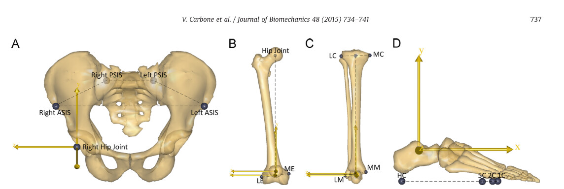
I always assumed that the reference frame were implemented according to the paper by Carbone et al. documenting the TLEM 2.0 but it doesn't seem to match what's reported in the paper:
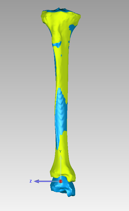
If I plot the segment reference frames in AnyBody
( for instance through:
Main.HumanModel.BodyModel.Right.Leg.Seg.Shank={
    AnyDrawRefFrame drw = {RGB = {1,0,0}; ScaleXYZ = {0.3,0.3,0.3};};};
but I also if I define a new RefNode in the segment with sRel = {0.0, 0.0, 0.0}; ),
I obtain the following reference frames:
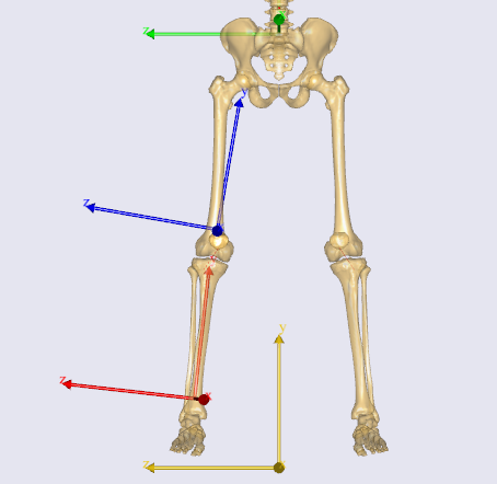
They are potentially oriented like the ones described Carbone et al. but they definitely do not have the same origins, for instance the intra-malleolar point for the tibia.
I also read the Klein Horsman paper on the original TLEM 1.0 but I couldn't really find how these segmental origins are defined.
Can someone help me clarifying how the default segment reference frame are defined?
And to match the definition of the paper by Carbone et al, should I just define a new ref frame in the correct origin, while maintaining the same relative segment orientation?
Thank you!
Enrico