I want to use AnyBody to calculate the muscle force and Joint moments from subjects walking at preferred speed using different shoes on a treadmill.
After setting up the necessary marker protocol and defining other parameters, using TLEM 2.0 and data from our lab's force plate, i was able to get results which have similar profiles with already published papers for a successful gait cycle for kinetics and kinematic studies.
The challenge is that i am unable to get successful gait cycle where a foot doesn't contact two force plates at instances of foot contact for some trials and subjects. With this challenge, it became imperative to rely on the Force plate GRF prediction, giving that i have seen a previous video where it was demonstrated to be acurate, upon a colleague's suggestion.
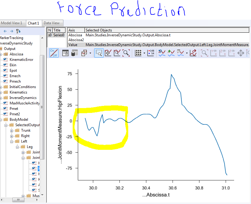
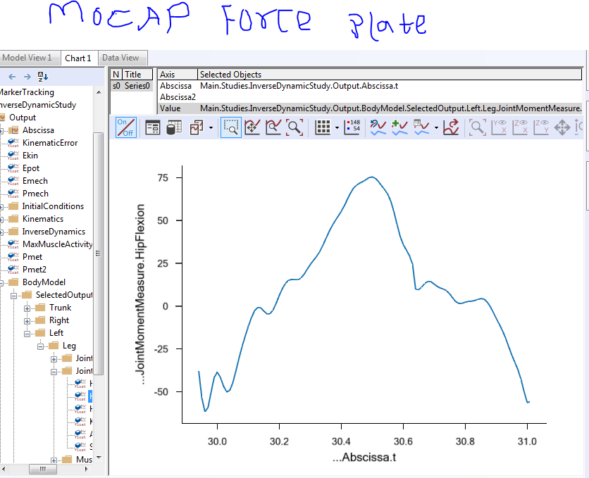
I followed the steps in the tutorial, set up my Normal direction as Z, according to our laboratory coordinate system. I decided to compare the results of the predicted forces with results of my simulation with our MOCAP Force plate data, then i realized differences in the graph profile.
I tried to upload my folder as zip, but it appears that new users are not allowed to. Therefore, i have uploaded the file on my OneDrive account for easy access. Here is the link: https://1drv.ms/u/s!Ag-WNImfEu3LhGA6aQ3ASw0Os0Fw?e=51n0e8
The bulk of the differences are seen at the initial contact phase. for example, the period beyond time 30.2 seems to be same. However, it is different before 30.2 (for Hip flexion moment).
I will attach screenshots here for your reference and quick look.
Please ensure the distance limits are correctly adjusted. Secondly since this is a treadmill you will need to adjust the ground speed to be the speed of the band. This can be done with in the file setting up the GRF prediction here you can set the property " GroundVelocity " to a vector with the speed in x,y,z....
So the code may look like this.
  FootPlateConditionalContact GRF_Prediction_Right(
  NORMAL_DIRECTION = "Y",
  NUMBER_OF_NODES = 25,
  NODES_FOLDER = FootNodes,
  SHOW_TRIGGER_VOLUME = ON,
  PLATE_BASE_FRAME = Main.EnvironmentModel.GlobalRef) =
  {
    CreateFootContactNodes25 FootNodes(foot_ref =
    Main.HumanModel.BodyModel.Right.Leg.Seg.Foot) = {};

    // Additional force plate settings
    Settings =
    {
      LimitDistHigh = 0.015; // Vertical height
GroundVelocity ={1,0,0};  //example 1 m/s in x direction
    };
  };`
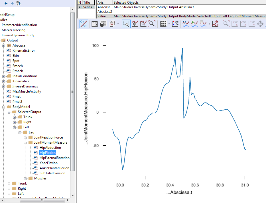
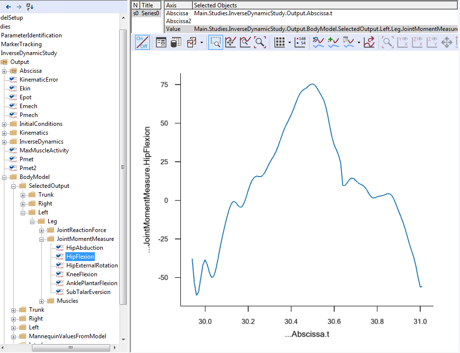
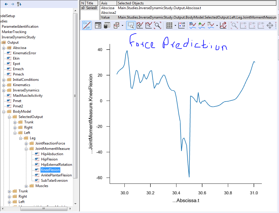
I implemented your suggestion, using Z as my normal direction according to our Lab's coordinate system. It improved the profile of the hip flexion moment. as shown below.
However, other outcomes like Knee flexion moment, hip abduction moment e.t.c. are not similar. I'd share a picture of the knee flexion moment here for your reference.