I have problems running my invers dynamics analysis. I am currently investigating muscle forces in patients with rotator cuff muscles tears. Therefore, I am changing muscle properties to Set value F0 = 0 in order to model an accurate complete rupture. If I change values of the supraspinatus and the infraspinatus, everything works fine. But if I also change the values of the teres minor fibers to 0, I always get an Error message: ERROR(OBJ.MCH.MUS4) : AnyMocapModel.any(64) : InverseDynamicStudy.InverseDynamics : Muscle recruitment solver : solver aborted due to singular KKT matrix
Does maybe somebody know why this happens and how I could prevent that?
This simply means the model failed to find a way to recruit the muscles which would create balance in your model.
In other words you have reduced the strength of the model too much, there is a DOF in the model which can not be balanced.
Teres minor can do external rotation on the humerus, maybe you need to have a different internal/external rotation of the humerus that would allow other muscles to have a moment arm for this DOF? will patients which these problems move the arm in the same way as a healthy?
No, affected shoulders have probably other kinematics than healthy ones. However, the model is already driven with individual motion capture data. I have changed now the center of rotation more medially and distally (because the patients have reverse shoulder prothesis), which resulted in inverse dynamics analysis until around 60° of abduction without error message...Therefore, I have to probably first set up a more accurate model. which will maybe not fail to find balance in the model.
I am thinking about trying to implement a simplified geometry of a reverse shoulder prothesis into my model? Do you think this is feasable?
This type of model will allow the join center to move a bit.
Please note that it will require ligaments to be correctly defined around the joint and it will slow down the analysis time significantly, and open up additional error modes such as joint dislocation. So the extra detail comes with a cost in terms of computation time and significantly added model complexity. You need to consider if this is the right path for this problem and the questions you want to answer and if you have the available time to make this model work.
Thanks for your advice. Yeah, I have not that much time available, however I will have a look at the webcast and tutorial.
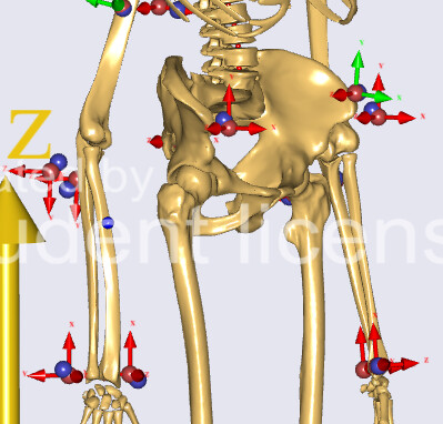
Anyway, yesterday I also run into another problem. Until now, I was never questioning the marker size in Anybody, because I thought that would not have a very big influence on the results. As I do not know if there will be an effect on the results or not, I just thought I will try to change the marker size. By default, the radius of the markers is 15mm and the experimental markers which were used for my data set have a radius of 7mm and 4.75mm. Therefore, I changed MarkerScaleXYZ, nevertheless the markers which are connected to MoCapDrivers do not change their size in the model view (The markers which are not connected to MocapDrivers change: see example on the right forearm). Is this just an issue of the model view or do I have to change also the size of the MoCapDrivers? If yes, do you know how? I found the Anyfloat variable Size in the model tree for the drivers, however they are not editable...
This is just a visual thing it will not impact results, the results are based on a measure from the center of the markers, so their size will not change anything.
To change them visually you will need to look into the CreateMarkerDriver class it seems it has a property called "DRAW_SCALE" which can be set from the marker protocol file. It will control both the size of the arrows and the spheres as i see the code.