How to add R_FTC and L_FTC markers in MarkerProtocol file

Greetings Dave,
I’ve made adjustments based on your feedback to improve the accuracy of the MoCap model.
I changed the contact direction to {2,0,1} instead of the default {0,1,2}.
I also increased UserDefinedLimitHigh to 1.5 and seemed to get a reaction from the contact points at Leg.
So I took the liberty to make the same changes in my SeatSupport.any and BackRestSupport.any.
I initially just changed the direction but realized I only get reaction from contact points at Seat and not BackRest so I changed the threshold for the contact in my BackRest alone respective to the distance I saw in the GUI.
The seat is individually fixed to the global ref using AnyKinEq with Reaction.Type = {On, On, On, On, On, On};.
Adding additional AnykinEq over constraints the model. The following is the code structure I am using now:

AnyKinLinear BackRestGlobalLinMeasure =
{
//RefFrames = ;
//viewKinMeasure.Visible = Off;
//Type = CartesianCoord;
//Ref = -1;
//LineLineDistanceAxes = {{x, x}};
//LineLineDistanceAxisLength = 10.0;
//AngularAxis = z;
AnyRefFrame &SegNode = Main.EnvironmentModel.EnvironmentModel.BackRest.BackRestSeatJntNode ;
AnyRefFrame &GroundNode = Main.EnvironmentModel.EnvironmentModel.GlobalRef.GroundNode ;
};

AnyKinRotational BackRestGlobalRotMeasure = 
{
  //viewKinMeasure.Visible = Off;
  Type = RotVector;
  //Axis1 = z;
  //Axis2 = y;
  //Axis3 = x;
  //DirCosineAxes = {{x, x}, {x, y}, {x, z}, {y, x}, {y, y}, {y, z}, {z, x}, {z, y}, {z, z}};
  //AngVelOnOff = Off;
  //AngVelGlobal = Off;
  AnyRefFrame &GroundNode = Main.EnvironmentModel.EnvironmentModel.GlobalRef.GroundNode ;
  AnyRefFrame &SegNode = Main.EnvironmentModel.EnvironmentModel.BackRest.BackRestSeatJntNode ;
};

AnyKinEq BackRestGlobalConst = 
{
  //viewKinMeasure.Visible = Off;
  MeasureOrganizer = {0, 1, 2, 3, 4, 5};
  //CType = ;
  //WeightFun = ;
  AnyKinMeasure &LinMeasure = Main.EnvironmentModel.EnvironmentModel.Jnt.BackRestGlobalLinMeasure;
  AnyKinMeasure &RotMeasure = Main.EnvironmentModel.EnvironmentModel.Jnt.BackRestGlobalRotMeasure; 
};

AnyKinLinear HeadRestGlobalLinMeasure = 
{
  //RefFrames = ;
  //viewKinMeasure.Visible = Off;
  //Type = CartesianCoord;
  //Ref = -1;
  //LineLineDistanceAxes = {{x, x}};
  //LineLineDistanceAxisLength = 10.0;
  //AngularAxis = z;
  AnyRefFrame &SegNode = Main.EnvironmentModel.EnvironmentModel.HeadRest.HeadRestBackRestJntNode ;
  AnyRefFrame &GroundNode = Main.EnvironmentModel.EnvironmentModel.GlobalRef.GroundNode ;
};

AnyKinRotational HeadRestGlobalRotMeasure = 
{
  //viewKinMeasure.Visible = Off;
  Type = RotVector;
  //Axis1 = z;
  //Axis2 = y;
  //Axis3 = x;
  //DirCosineAxes = {{x, x}, {x, y}, {x, z}, {y, x}, {y, y}, {y, z}, {z, x}, {z, y}, {z, z}};
  //AngVelOnOff = Off;
  //AngVelGlobal = Off;
  AnyRefFrame &SegNode = Main.EnvironmentModel.EnvironmentModel.HeadRest.HeadRestBackRestJntNode ;
  AnyRefFrame &GroundNode = Main.EnvironmentModel.EnvironmentModel.GlobalRef.GroundNode ;
};

AnyKinEq HeadRestGlobalConst = 
{
  //viewKinMeasure.Visible = Off;
  MeasureOrganizer = {0, 1, 2, 3, 4, 5};
  //CType = ;
  //WeightFun = ;
  AnyKinMeasure &LinMeasure = Main.EnvironmentModel.EnvironmentModel.Jnt.HeadRestGlobalLinMeasure;
  AnyKinMeasure &RotMeasure = Main.EnvironmentModel.EnvironmentModel.Jnt.HeadRestGlobalRotMeasure; 
};


AnyKinLinear LegRestGlobalLinMeasure = 
{
  //RefFrames = ;
  //viewKinMeasure.Visible = Off;
  //Type = CartesianCoord;
  //Ref = -1;
  //LineLineDistanceAxes = {{x, x}};
  //LineLineDistanceAxisLength = 10.0;
  //AngularAxis = z;
  AnyRefFrame &SegNode = Main.EnvironmentModel.EnvironmentModel.LegRest.LegRestSeatJntNode ;
  AnyRefFrame &GroundNode = Main.EnvironmentModel.EnvironmentModel.GlobalRef.GroundNode ;
};

AnyKinRotational LegGlobalRotMeasure = 
{
  //viewKinMeasure.Visible = Off;
  Type = RotVector;
  //Axis1 = z;
  //Axis2 = y;
  //Axis3 = x;
  //DirCosineAxes = {{x, x}, {x, y}, {x, z}, {y, x}, {y, y}, {y, z}, {z, x}, {z, y}, {z, z}};
  //AngVelOnOff = Off;
  //AngVelGlobal = Off;
  AnyRefFrame &SegNode = Main.EnvironmentModel.EnvironmentModel.LegRest.LegRestSeatJntNode ;
  AnyRefFrame &GroundNode = Main.EnvironmentModel.EnvironmentModel.GlobalRef.GroundNode ;
  
};

AnyKinEq LegRestGlobalConst = 
{
  //viewKinMeasure.Visible = Off;
  MeasureOrganizer = {0, 1, 2, 3, 4, 5};
  //CType = ;
  //WeightFun = ;
  AnyKinMeasure &LinMeasure = Main.EnvironmentModel.EnvironmentModel.Jnt.LegRestGlobalLinMeasure;
  AnyKinMeasure &RotMeasure = Main.EnvironmentModel.EnvironmentModel.Jnt.LegGlobalRotMeasure; 
};

However, I presume they are linked to each other and the Seat via joint definitions. 1) Is the approach right?

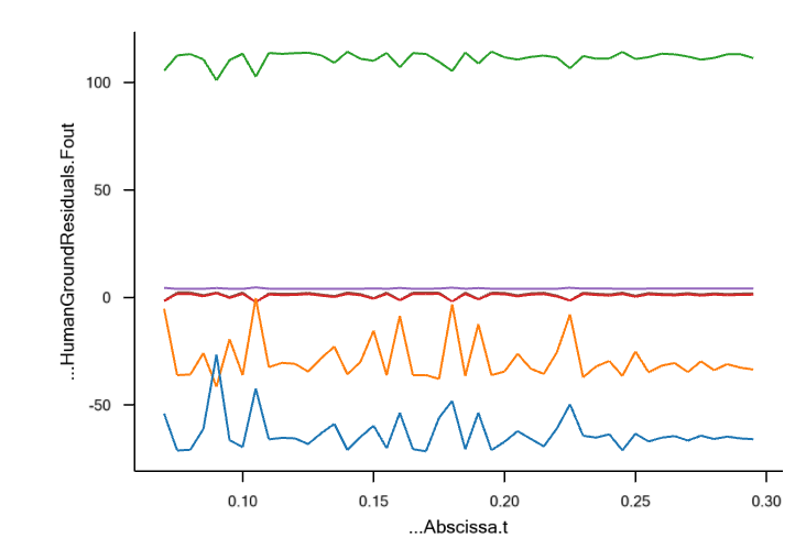
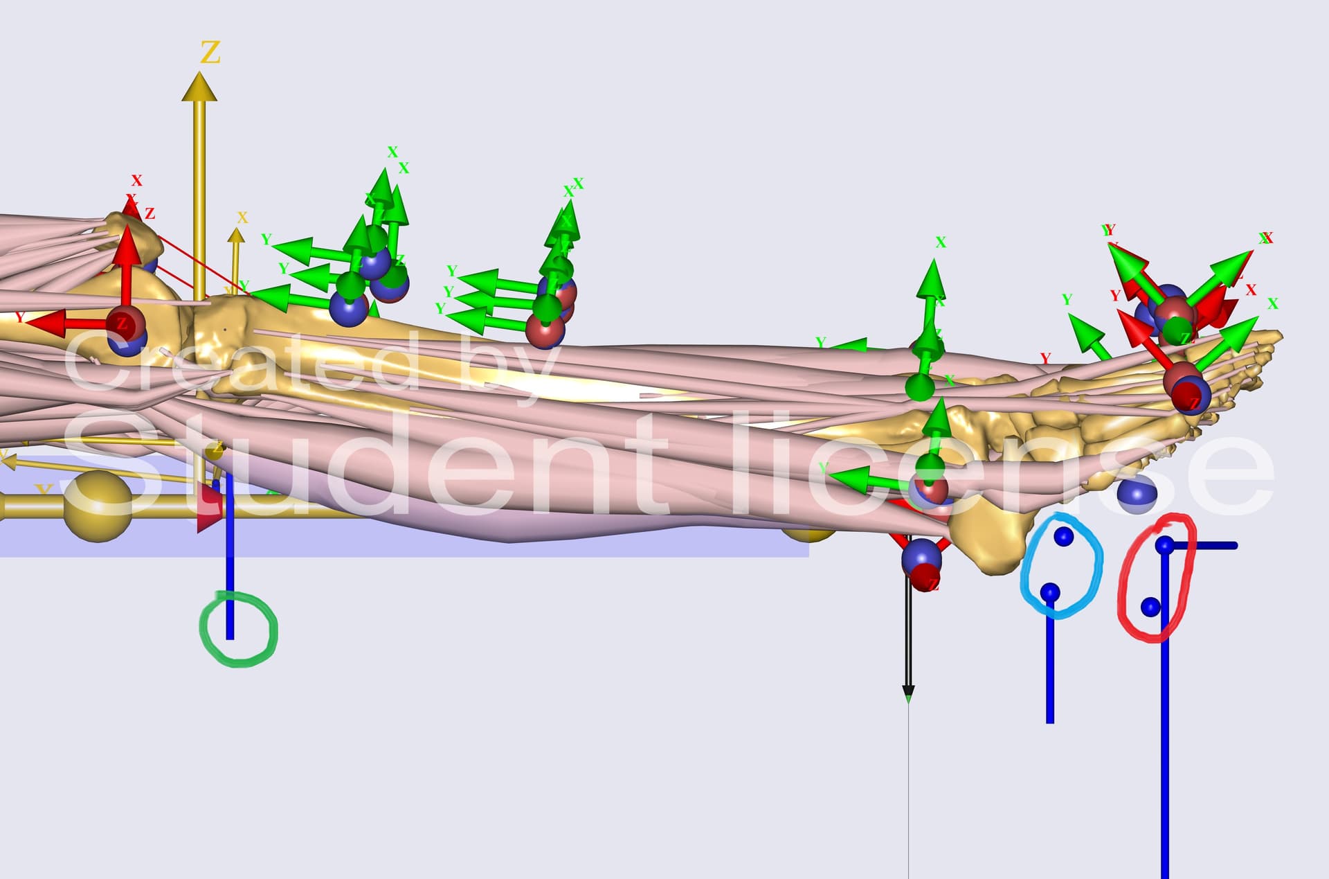
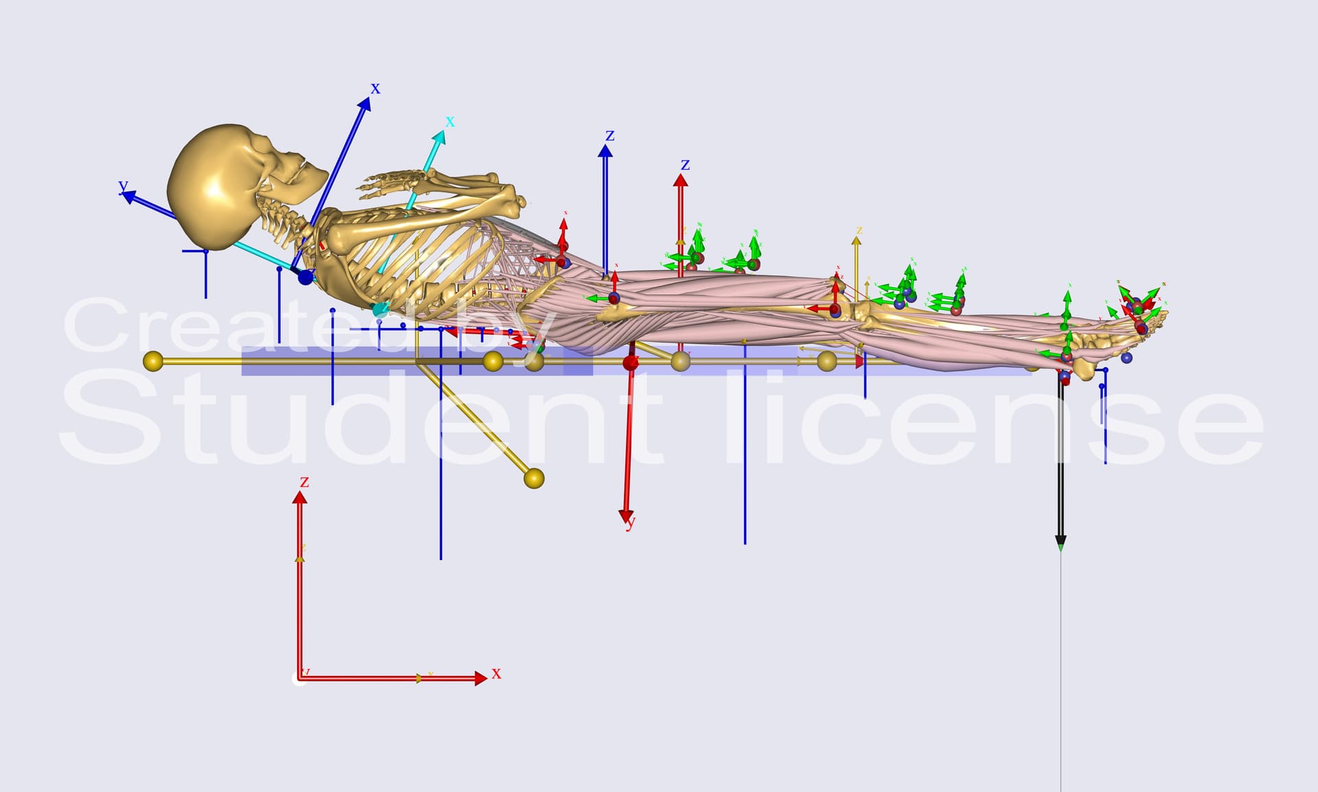
I am attaching a picture of my model now after the InverseDynamics Study.

The results seem to be slightly better now. When compared to the ID study of SPLB model they seem to be in close - medium vicinity. However, the right leg seems to exhibit more joint reaction force compared to the left when it is the left ankle that is under load. 2) How do I validate the results?

Please let me know if you need additional information.

Thank you.
With Regards,
Romy Jemals.

Hi Romy,

  1. You should either fix all segments individually to global ref, or one segment to the global ref and the others with joints to this root segment (so you make a chain of segments). Having both will over constrain the model. I also assume that the seat model has all the joints, but I don't know that specifically in your model. I am sure you can identify the joints and drivers to position the seat.
  2. Validation of the model can be quite tricky. You are already comparing your results to the SPLB model, then, if you have some other measured data that you can use to check the outputs of the simulation. Typically, people will use EMG, but you should also be aware of the limitations of using EMG for validation. You could also think about validation using trends. You can also see a list of validation publications on our website for inspiration.

Best regards,
Dave

Greetings Dave,

  1. I presume I have used the first approach. The seat is fully constrained to the global reference using AnyKinEq, which applies six constraints (MeasureOrganizer = {0,1,2,3,4,5}) with reactions turned on (Reaction.Type = {On, On, On, On, On, On}).
    The backrest, headrest, and leg rest are also each directly constrained to the global reference using 'AnyKinEq' with just MeasureOrganizer = {0, 1, 2, 3, 4, 5}; Should I have Reaction type set to ON?
    I vaguely remember I get an over constrained model if I use it.
    All the segments have all the joints as in SPLB model.

  2. To be clear, not comparing but using the SPLB model with the load acting on the left ankle as a benchmark/reference. I do not have measured data but I will check the link you suggested.

Thank you.
With Regards,
Romy Jemals

Greetings again Dave,

I ran the model with (Reaction.Type = {On, On, On, On, On, On} ) for other segments too. The inverse dynamics study ran good.
I apologize for the earlier confusion about it being over-constrained. It must have been an earlier version of the working model.
The results look better and in the benchmark region of the SPLB model but there is still noticeable variations in magnitude and/or directions between the both.
Is that reasonable?
The SPLB model has been modified with my test subject's body mass and a load of -39.24N acting on the left ankle.

I have one more question to add:
Should I run my MoCap model with/without HGR? If yes, just Pelvis or Pelvis and Trunk?
I have attached the Human Ground Residuals chart below.

Thank you.
Best Regards,
Romy Jemals

Hi Romy,

I am sorry, I didn't understand which results you are talking about when you mention variation in directions. The results from the human model (for example joint reaction force) should be consistent in direction. But the results concerning the seat interaction with the human model can have difference, especially in directions. This is a simple consequence of the coordinate system used during your measurements being different than those in the model. You need to make sure you are comparing the right directions, in which case you should decide directions based on the human model.

Have you also removed the footrest in the SPLB model as is the case in your model?

Regarding HGR, the general advice is to run with HGR for mocap models, and where depends on what exactly you are interested in studying. In your model, you should run without the HGR because your model is supposed to be resting on a bed, so it's fairly static, and is supported on multiple points. Somehow, the values look a bit too high for HGR in your model.

Best regards,
Dave

Greetings Dave,

  1. I was talking about Joint reaction forces (Magnitude and/or Direction) between the SPLB model and mine.

  2. JRF in right leg is comparatively higher than JRF in left leg, so is Muscle activity, respectively . PelvisRotZ decreases, PelvisPosY has a tiny upward shift, No significant PelvisPos X or Z shift.
    So I presume the pelvis is mostly stable, with only a small frontal tilt adjustment and very little twisting.
    I also presume since the left leg is being pulled down by the external load which explains the reduced muscle activation which in turn reduces the joint reaction forces. So the body might be slightly shifting weight to the right side for stability. Is my hypothesis right?

  3. My model does not have a foot rest as the test scenario did not need one but I have not removed the foot rest in SPLB model. Thank you for pointing it out. Silly from my end, I would do it right away and proceed to compare results.

  4. Yes, the values look a bit high for the HGR which I could not comprehend why. I will run one without the HGR to see if it makes the results better.

Thank you.
With Regards,
Romy Jemals

Hi Romy,

I think it's strange that you see the unloaded leg with higher muscle activation and joint reaction force. I was just looking at the last image you shared from the model to check if the external load is applied correctly. It seems to be. At least the direction of the external load on the ankle looks correct. One other thing I noticed is that maybe the model doesn't have any support on the lower end of the lower leg. Can you try to add a couple of support points on the lower end of the shank, in a way that it corresponds to where the bed ended?

Best regards,
Dave

Greetings Dave,

  1. What do you mean by, 'At least the direction of the external load on the ankle looks correct.'?

  2. I added a low support node on the lower end of shank, in a way that it corresponds to where the bed ends (somewhere slightly before it).
    However, I am just noticing a major anomaly in the model. I will explain them using a couple of pictures below.


    However, post marker tracking this is how they look,

    The red highlights the LowSupportNode and the blue highlights the SupportNode from Shank. Seems a bit weird that they are down there near the Ankle?

    The green highlights the Normal force from ThighSupportFrontR. I cant seem to understand how the nodes are not where they are supposed to be?
    I must be overlooking something.

With Regards,
Romy Jemals

Greetings again Dave,

Continuation of 2): I figured out why. I used the same sRel as of the SPLB Model assuming it would be the same but I did change it to suit my model now and this is how it looks after Marker Tracking process.


Thank you.

However, my question now is how you choose AnyIntArray Direction={,,}; //first element gives normal direction.

I went with {2,0,1} instead of the default {0,1,2} listening to your advice earlier. As seen in the figure, my LegRest RefFrame is Z pointed up, X pointing towards the ankle and Y inwards the screen with,
Axes0 = {{1.0, 0.0, 0.0}, {0.0, 1.0, 0.0}, {0.0, 0.0, 1.0}};
My Seat and BackRest are also defined the same.
which is why I chose {2,0,1}

I was curious and ran a InverseDynamics Study with {0,1,2} in just LegSupport (without the LowSupportNode) and the JRF and Muscle activity in Right leg are higher than Left leg which is the trait we are looking for?

Changing it throughout in all Segments to make it uniform makes it messy as before with unloaded Right higher than loaded Left left.

How do I go about this?

Thank you.
With Regards,
Romy Jemals

Hi Romy,

I was in doubt about the direction of the ankle load that you are applying since your results are not reflecting what you want to do. But, I think it's the black arrow at the ankle in your screenshot and that looks ok.

Regarding the Direction vector, it determines the normal and shear direction for the contact force between the bed and the human. The indices 0,1,2 refer to x,y and z axes of the base object, which should be the bed. So, if you have the Z axis of the bed pointing upwards, then you should use Direction = {2,0,1}; The sequence of the second and third indices (0,1) doesn't matter so much as they determine the shear force.

I tried to simulate this external load in the SPLB model and removing the foot rest. I can see higher muscle activation and jrf on the loaded leg. The differences are not large, so like you say, it can easily be compensated by the change in posture that you noticed.

Best regards,
Dave

Greetings Dave,

Yes it is black arrow at the ankle that depicts the external load.

Thank you for the validation and clarity regarding the direction vector. I have a question to add on to that:

I was curious and ran a quick trail: SupportNode in Shank with Direction = {2,0,1}; and LowSupportNode with Direction = {0,1,2}; gives expected results with higher JRF and muscle activity except a said few (Knee_AnteroPosteriorForce,Ankle_* and HipFlexorMuscleActivity). I am attaching the picture below.

Is this mixed setup acceptable and reasonable for me to believe and proceed with since it gives expected results?

Having it uniform as Direction = {2,0,1}; in all my supports produces higher JRF and muscle activity in unloaded leg. How do you reckon I proceed?

Also why do selected contact points have reaction and few do not?
For example, ThighSupportFrontL has a normal force drawn in GUI while ThighSupportFrontR has none.

One additional information is these trails (above few too) are now with HGR set to 'Trunk'. It was a visual judgement made after viewing results with HGR set to Pelvis, Trunk, WeakResiduals and without.

Regarding the differences between the model noted and thank you for taking your time, appreciated. :slight_smile:

Thank you.
With Regards,
Romy Jemals