I want to look at the joint angles in comparison to the digital model alaska/Dynamicus.
For the data to be comparable, I am trying to find the reference frames of each joint.
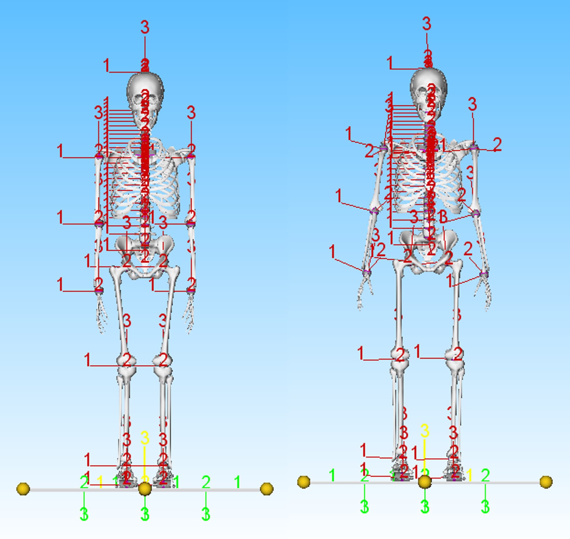
In alaska/Dynamicus there is a default state (all angles zero) where the joint ref frames look like the ones on the left, and after loading the initial position, they look like the ones on the right:
I am using the Plug-in-gait_MultiTrial example for my mocap data (different load handling trials) with a neutral position like in the right picture as the base for the initial position and parameter identification.
My question is now, is there a default view like the left picture in AnyBody and also for the right one? I have tried with a Standing Model from the AMMR with all angles set to 0, but I am unsure if in that case the reference frames would be like the ones in the picture. Also is there a quick way to show/hide the ref frames? I am currently (de)activating them manually for each joint in the Interface.any or Jnt.any files, is that the correct way (or which one is more correct as they generate different ref frames?)?
Looking forward to hearing from you, thanks in advance!
Welcome to the AnyScript forum and apologies for the delay in the response.
I think there is no shortcut way to set the model view to show only the reference frame of the joints. You can add extra code to set the visibility of the reference frames to On.
You can explore to reference frame in the model tree, right click and insert object name. Then add .viewRefFrame.Visible = On;
It's a little bit time consuming in the beginning but then you can reuse the codes. Additionally, you can use #define and #if statements (see the preprocessor section in the reference manual) to control the drawings in groups
Normally, the reference frames in the interface folder are used by mannequin drivers. I think these could be of interest to you as they will correspond to the joint angles that you set.
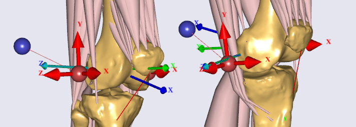
I have tried to show all the ref frames for the joints, but I have some more questions. For example for the knee, I can activate both the ShankNode and the ThighNode and they are different:
My question is now, which one is used? (In this case the z axis for the flexion is the same, but the x and y axis differ and for other joints more than the flexion are interesting.)
The same applies to all other kinematic measures in the joints. I don't know if my thinking is wrong, but I need the one ref frame used by each joint like in the pictures from the Dynamicus human model to compare the measures.
If we talk about the knee joint, the joint is made between two reference nodes. One is on the thigh segment and the other is on the shank segment. They have their z axis aligned as you noticed. Z axis is the flexion axis. The x axis is the anterior posterior direction and the y axis is the longitudinal direction of the corresponding segment. If you set the knee flexion angle to zero, then these two reference nodes would be exactly aligned, including the x and y axes. But if you change the knee flexion angle, you will see a difference in their x and y axes. But that's normal as one shows orientation of the thigh and the other shows the orientation of the shank.
All the classical joints are made between two reference frames on two segments, and then it's a question about picking the right one according to your needs. I am not aware of how these reference frames are defined in Dynamicus so I can't help you exactly. From the image, it looks like it is using the knee reference frame on the shank. But that's just my guess You will have to figure out how these reference frames are defined in Dynamicus and pick the corresponding one in AnyBody.
If it's really needed, you can also create new reference frames on the AnyBody Model that will match with Dynamicus system.
thanks again for your answer, I think I understand it now For the lower extremities this works very well if I set the angles to zero.
The question I now have is that for the upper extremities there are several possible nodes to display that show different axes/directions. I know that especially the shoulder complex is not as easy as the knee joint, but could you help point me to the right ones to display for the GlenoHumeral, SternoClavicular and elbow movements?
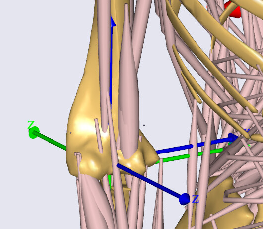
For example the right elbow:
These are
humerus = {AnyDrawRefFrame drw={RGB={0,0,1};Visible = On;}; };
ulna = {AnyDrawRefFrame drw={RGB={0,1,0};Visible = On;}; };
in AnyKinMeasureOrg ElbowFlexion when the angles are set to zero.
The image looks like it is taken at load time position...? You will need to run the kinematics analysis to ensure that the joints and drivers are correctly analyzed. Some joints may be a little bit off at load-time, like you see in this case of the elbow.
For the glenohumeral joint, I would point you to look at the BodyModel.Interface folder in the model tree. From there, you can see the definitions of the different measures, and trace to the reference frames defined on the humerus. Maybe that helps you?