Joint definition using rotational matrices over time

Hello AnyScript forum,

I would like to change the definition of the knee joint (and later the patella) by exploiting the coordinates in time of the rotation of the tibia with respect to the femur during passive flexion. I have already transformed these coordinates into 4x4 matrices that, if desired, could be parameterized into the three rotation angles and three displacements for each time step. In order to use this data is it okay to define a standard joint? Also, can I define the joint by using motion over time with matrices or do I have to interpolate the angles and define the equation over time?

I hope to hear from you soon,
Best regards,
Vera

Hi Vera,

A standard joint will lock all six dof to zero so that will not work in the case as I understand the problem.

I think you would need to define an AnyKinLinear and AnyKinRotational between femur and tibia, then use an AnyKinEqInterpolDriver for driving these measures to the data you have.

The more complex part is to determine a good way to transmit the knee reaction forces.. by default the driver will supply all reactions unless these are disabled using Reaction.Type= {Off.....} inside the driver.

I these ways:

  • Create a custom version of the knee joint, basically use an AnyReacForce object on the measures in the existing knee joint this would do reactions but add no kinematic constraints.
  • If the measures you have, has a DOF which can be considered to represent the knee axis the use the AnyReacForce on all other DOF than the one representing flexion.

Hope it made sense.

Best regards
Søren

Hi Søren,

Thank you very much for your answer!

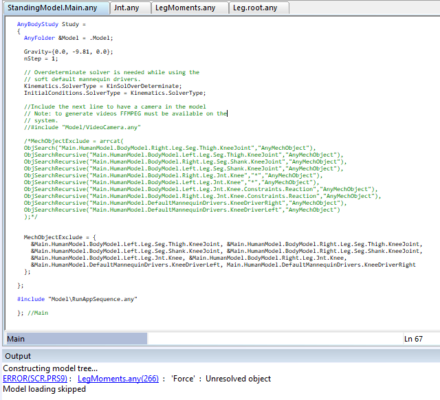
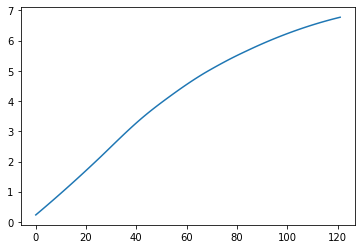
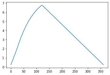
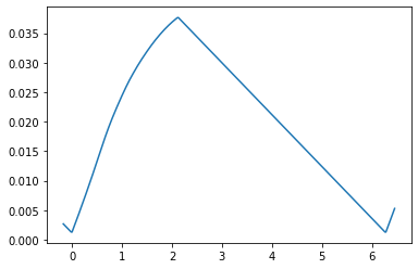
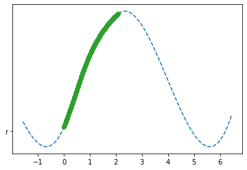
I basically have six graphs; three with rotation angles with respect to the three axes and three with translations. As for the flexion-extension, this is a linear function from 0° to 120° as a given motion, while the others were obtained as outputs.
So, if I understand your answer correctly I don't have to define knee joint, but I have to start from the definition of reaction force, right? Or do I need to define the AnyReacForce together with the RevoluteJoint?

AnyReacForce Knee = {
AnyRefNode &ThighNode = ..Seg.Thigh.KneeJoint;
AnyRefNode &ShankNode = ..Seg.Shank.KneeJoint;
//AnyDrawStdJoint Knee = { };
}; // End of knee

AnyKinEqSimpleDriver KneeFlexion = {
DriverPos = {-120pi/180}{0,0,1};
AnyReacForce &Joint = .Knee;
};

AnyKinEqInterPolDriver KneeAbd = {
T = {0.0 , 0.00833333, 0.01666667, 0.025 , 0.03333333,
...
0.95833333, 0.96666667, 0.975 , 0.98333333, 0.99166667,
1}*Main.Study.tEnd;
Data = {{0.23290907, 0.303203, 0.37384821, 0.44484215, 0.51618176,
...
6.7553693, 6.7758715},0,0}*pi/180;
Type = Bspline;
BsplineOrder = 4;
AnyReacForce &Joint = .Knee;
};
AnyKinEqInterPolDriver KneeRot = {
T = {0.0 , 0.00833333, 0.01666667, 0.025 , 0.03333333,
...
0.95833333, 0.96666667, 0.975 , 0.98333333, 0.99166667,
1}*Main.Study.tEnd;
Data = {0,{-6.5135326, -6.6241747, -6.7315992, -6.8358009, -6.936774,
...
-1.408883, -1.255194, -1.0988564, -0.93985359, -0.77817159},0}*pi/180;
Type = Bspline;
BsplineOrder = 4;
AnyReacForce &Joint = .Knee;
};

AnyKinEqInterPolDriver Xtrasl = {
T = {0.0 , 0.00833333, 0.01666667, 0.025 , 0.03333333,
...
0.95833333, 0.96666667, 0.975 , 0.98333333, 0.99166667,
1}*Main.Study.tEnd;
Data = {{-2.948783, -3.112774, -3.2785592, -3.44613, -3.6154764, -3.7865873, -3.959451,
...
-25.512276, -25.655722, -25.796707, -25.93523, -26.071288, -26.20488, -26.336007, -26.464668, -26.590862, -26.714588},0,0};
Type = Bspline;
BsplineOrder = 4;
AnyReacForce &Joint = .Knee;
};

AnyKinEqInterPolDriver yTrasl = {
T = {0.0 , 0.00833333, 0.01666667, 0.025 , 0.03333333,
...
0.95833333, 0.96666667, 0.975 , 0.98333333, 0.99166667,
1}*Main.Study.tEnd;
Data = {0,{34.227079, 34.241116, 34.254381, 34.266873, 34.278587, 34.28952,
...
28.894067, 28.749905, 28.60389, 28.456032, 28.306341, 28.15483, 28.001508, 27.846386},0};
Type = Bspline;
BsplineOrder = 4;
AnyReacForce &Joint = .Knee;
};

AnyKinEqInterPolDriver zTrasl = {
T = {0.0 , 0.00833333, 0.01666667, 0.025 , 0.03333333,
...
0.95833333, 0.96666667, 0.975 , 0.98333333, 0.99166667,
1}*Main.Study.tEnd;
Data = {0,0,{-1.9686421, -1.7056788, -1.4509027, -1.2043015, -0.96586561, -0.73558467,
...
3.5723669, 3.6666611, 3.7647059, 3.8665014}};
Type = Bspline;
BsplineOrder = 4;
AnyReacForce &Joint = .Knee;
};

That's how I interpreted your answer and edited the jnt.any file, is that what you meant?
In doing so, however, I get this error, so I don't understand if I can not define the knee as a joint

image

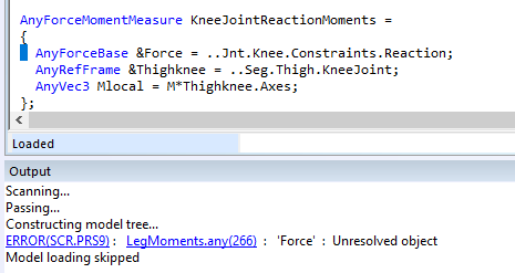
Thank you very much!

Best Regards, Vera

Hi Vera,

Here are some comments:

The code below will not work, the anyreacforce needs to work on measures not just frames.

AnyReacForce Knee = {
AnyRefNode &ThighNode = ..Seg.Thigh.KneeJoint;
AnyRefNode &ShankNode = ..Seg.Shank.KneeJoint;
//AnyDrawStdJoint Knee = { };
}; // End of knee

The AnyReacForce will need to work on an AnyKinLinear and AnyKinRotational it can not work directly on the nodes.

I have tried to write some code below for you to get the idea, sorry for any typos

AnyKinLinear Lin ={
Ref=0;  //use coordinate system of ThighNode ??? depends on your data...
AnyRefNode &ThighNode = ..Seg.Thigh.KneeJoint;
AnyRefNode &ShankNode = ..Seg.Shank.KneeJoint;
};

AnyKinRotational Rot ={
AnyRefNode &ThighNode = ..Seg.Thigh.KneeJoint;
AnyRefNode &ShankNode = ..Seg.Shank.KneeJoint;
Type=RotAxesAngles; //  Ensure you choose the right tyope of measure here like you have your data! 
//Sequence is also important  see documentation on the AnyKinRotational object  default seqeucne in z,y,x
};

//make a measure excluding flexion assuming this is first axis is Z  note  0 component not listed in measureorg
AnyKinMeasureOrg  KneeReactionDOF ={
AnyKinLinear &ref1=.Lin;
AnyKinRotational &ref2=.Rot;
MeasureOrganizer ={1,2,3,4,5};
};


AnyReacForce Knee = {
AnyKinMeasureOrg  KneeReactionDOF ={
}; // End of knee

AnyKinEqSimpleDriver KneeFlexion = {
DriverPos = {-120pi/180}{0,0,1};
AnyReacForce &Joint = .Rot;
MeasureOrganizer ={0};
Reaction.Type={Off};  //we do not want reactions on the drive
};


Then do the other dof 

AnyKinEqInterPolDriver KneeAbd = {
T = {0.0 , 0.00833333, 0.01666667, 0.025 , 0.03333333,
...
0.95833333, 0.96666667, 0.975 , 0.98333333, 0.99166667,
1}*Main.Study.tEnd;
Data = {{0.23290907, 0.303203, 0.37384821, 0.44484215, 0.51618176,
...
6.7553693, 6.7758715},0,0}*pi/180;
Type = Bspline;
BsplineOrder = 4;
AnyKinRotational &ref=.Rot;
MeasureOrganizer ={1};  //???
Reaction.Type={Off};  //we do not want reactions on the drive
};

AnyKinEqInterPolDriver KneeRot = {
T = {0.0 , 0.00833333, 0.01666667, 0.025 , 0.03333333,
...
0.95833333, 0.96666667, 0.975 , 0.98333333, 0.99166667,
1}*Main.Study.tEnd;
Data = {0,{-6.5135326, -6.6241747, -6.7315992, -6.8358009, -6.936774,
...
-1.408883, -1.255194, -1.0988564, -0.93985359, -0.77817159},0}*pi/180;
Type = Bspline;
BsplineOrder = 4;
AnyKinRotational &ref=.Rot;
MeasureOrganizer ={2};  //???
Reaction.Type={Off};  //we do not want reactions on the drive
};


Then also add linear drivers using "Lin" measure

Hope it makes sense.

You will also need to exclude the existing knee joint, the easiest way to do that would be to use the MechObjectExclude in the study, please see reference manual for how to do this. In this way you will avoid that the code will complain about the missing knee joint object. It will keep existing in the tree structure but it will not be part of the study you exclude it from. In this way you can avoid modifying the body model files and keep the changes in your own new files.

Best regards
Søren

Hello Søren,

Thank you very much for your help!

I am now trying to exclude the previous knee joint, following the example "ClassExamples.AnyBodyStudy.MechObjectExclude" and trying to include all the objects related to the knee joint in this way:

As you can see at the bottom I still have the same error, even if I specified to exclude "Main.HumanModel.BodyModel.Right.Leg.Jnt.Knee.Constraints.Reaction", that is how the object Force is defined. I tried both the method, the current and the commented one. Could you please help me also with this?

Furthermore, with this definition of the joint will I still be able to give to the model whatever movement I want or just the movement related to a knee flexion from 0° to 120°?

Thank you,
Vera

Hi Vera,

Please try to exclude your changes and ensure you have a running model.

The only explanation I can see for the error you get is that the knee joint has been out- commented in the script?

The exclusion using mechobjectexclude should not have this efffect... it will simply ensure the object is doing nothing... but it will still be in the modeltree etc...

You will also need to exclude the Constraints.Reactions from the knee joint. (nothing to do with the load error)

Concerning the last question...

As i understand the data you have this is simply function of time? not the angle flexion angle?

If you instead have data depending on the flexion angle you can do something along these lines... (not exactly trivial)


AnyFunInterpol   KneeAbd_KneeFlexion_Function  ={
T = {-0.5,0,0.25,0.5,0.75,1,1.5}*pi;  //  This represents kneeflexion angle posibilities needs to be wide... //should be  have finer discretization also 
Data={{1,1,1,1,1,1,1}} ;   // sample data ... represent kneeAbd for associated kneeflexion (T value)
};

//measure which takes knee flexion through the intepolation function above and give a measure for this 
AnyKinMeasureFunComb1 KneeAbd_Flexion=  {
  Functions =  KneeAbd_KneeFlexion_Function;
  AnyKinMeasure &ref=Main.HumanModel.BodyModel.Interface.Right.KneeFlexion;
};

AnyKinMeasureOrg KneeAbuction  ={
AnyKinRotational &ref=.Rot; //the rot measure for earlier
MeasureOrganizer={?};  //should represent abduction 
};


//measure diff btw the kneeabduction measure and the measure depending on kneeflexion 
//AnyKinMeasureLinComb  KneeAbduction_diff ={
   AnyKinMeasureOrg &ref=.KneeAbuction ;
   AnyKinMeasureFunComb1   &ref2=.KneeAbd_Flexion; 
Coef ={1,-1};
OutDim=1;
};

//constrain this measure to be zero means the kneeabduction will now follow as function of knee flexion
AnyKinEqSimpleDriver Constrain_KneeAbduction   ={
AnyKinMeasureLinComb  &ref=.KneeAbduction_diff ;
DriverPos={0};
DriverVel={0};
Reaction.Type={Off};
};

sorry for any possible typos....

Best regards
Søren

Hello Søren,

Thank you very much for your prompt reply.

I was able to load the model thanks to your suggestions. Now, however, when I try to run it, it has problems interpolating the data. For example, the flexion-abduction curve should be something like this:
image
But when I run the application, I have this error:
"ERROR(OBJ1) : Jnt.any(89) : KneeAbd_KneeFlexion_Function : Parameter has an invalid value for this interpolation; extrapolations are not allowed."
I am pretty sure that T and Data have the same number of elements, so I am not sure what that means. Here is my script, so maybe it's easier to analyze my mistakes.
Jnt.any (43.8 KB)

Thank you again for your help!
Kind regards,
Vera

Hi Vera,

This error means that the somehow the kinematic solver tried to use the interpolation function outside its valid range. Imagine that when the kin solver resolves constraints it iterate it way to the solution that full fills all constraints, on this way it may try out solutions that you would not think about like eg. flipping in the knee. For this reason the T vector of the interpolation function needs to "slack" in the ends. It is not enough to cover the reasonable knee range you need to also provide T values for the case that the solver wanted to try out something outside the range... So ideally you would like T to cover full circle, I know you to not have reasonable data outside range but this does not matter the data could be just constant like the first element and last element extrapolated.

Hope it makes sense.

Best regards
Søren

Hello Søren,

I added some values to the curve in order to reach the 2*pi in flexion. So now my abduction-adduction curve is like this:
image
But I still have the same error. I also tried only with constant values, like the first and the last elements extrapolated as suggested, but again this error happens. Is this the right solution or did I misunderstand your answer?

Thank you,
Vera

Hi Vera,

Please also try to add a T values that are negative otherwise zero is on the border of the array.
Also ensure you are correct about the rotaional units... i see the graphs in degrees the rotational measure will use radians

Best regards
Søren

Hi Søren,

Thank you very much for your answer.

I added 10 degrees of freedom before and after the entire circle. now i have 380° of flexion from -10° to 370°, expressed in radians. for each flexion degree, the abduction and intra-extra rotation and the three translations.

For example, my abduction function now are written like this:

AnyFunInterpol KneeAbd_KneeFlexion_Function ={
T = {{-0.05555555555555556, -0.05, -0.044444444444444446, -0.03888888888888889,
...
,2.0444444444444447, 2.0500000000000003, 2.055555555555556}pi;
Data={{0.0026130849289874537, 0.0024665131899641564, 0.002319941450940859,
...
0.0015870827558243713, 0.0014405110168010716, 0.0012939392777777778}}pi;
Type = Bspline;

BsplineOrder = 4;
};

image

But I still have the same error:"Parameter has an invalid value for this interpolation; extrapolations are not allowed.".
Furthermore, as the rotation is in radiants, the translation is in meters, isn't it?

Best Regards,
Vera

Thank you Søren,

I added other negative values, till -90° and I also tried to modify the added values in such a way as to provide AnyBody with a curve that was perhaps easier to interpolate
image

In this way I don't have anymore that error, so thank you very much for your help!

But I have another error that seems to be not only related with the definition of the knee joint, but all the joints:

  1. Operation Sequence: (Operation: Main.RunApplication):
    0.0) Operation Sequence: (Operation: Main.HumanModel.Calibration.CalibrationSequence):
    0.0.0) Dummy operation: (Operation: Main.HumanModel.Calibration.CalibrationSequence.PlaceHolderOpr):
    1.0) InverseDynamics (Operation: Main.Study.InverseDynamics):
    1.0.0) PreOperation (Operation: Main.Study.InverseDynamics.PreOperation):
    1.0.0.0) InitialConditions (Operation: Main.Study.InitialConditions):
    1.0.0.0) ...Design variables have been updated.
    1.0.0.1) ...Load-time positions have been re-established.
    Progressing to solve kinematic optimality conditions and hard constraints.
    Progressing to solve kinematic optimality conditions and hard constraints.
    Progressing to solve kinematic optimality conditions and hard constraints.
    Progressing to solve kinematic optimality conditions and hard constraints.
    Failed to solve kinematic optimality conditions and hard constraints after 5 fallback attemps.
    Constraint violations for study 'Main.Study' :
    Constraint #23 is above tolerance 1e-06, error = 0.009732, constr. #2 in 'Main.HumanModel.BodyModel.Trunk.JointsLumbar.SpineRhythmDrv'.
    Constraint #26 is above tolerance 1e-06, error = 0.084927, constr. #5 in 'Main.HumanModel.BodyModel.Trunk.JointsLumbar.SpineRhythmDrv'.
    ...
    Constraint #584 is above tolerance 1e-06, error = 0.069966, constr. #0 in 'Main.Model.ModelEnvironmentConnection.Left.ToeDirectionConstraint'.
    Constraint #585 is above tolerance 1e-06, error = 0.004319, constr. #1 in 'Main.Model.ModelEnvironmentConnection.Left.ToeDirectionConstraint'.
    ERROR(OBJ.MCH.KIN3) : StandingModel.Main.any(55) : Study.InitialConditions : Kinematic analysis failed in time step 0 : Position analysis is not completed

Could you please help me with this?

I hope to hear from you soon.
Best regards,
Vera

Hi Vera,

I am so sorry, your previous post was completely missed! I am glad that you were able to solve the interpolation issue.

Regarding the error in kinematics analysis, it is very likely to come from the changes you have made. The other joints and drivers just end up with errors larger than the allowed tolerance. It is a little bit hard to identify the possible errors but here are some thoughts:

  1. Your load-time position of the knee is too far from the solved position - but is probably not the case if you are starting at 0 degrees of flexion as I see from the graphs.
  2. You are using the standing model, which constrains the feet to the ground and the centre of mass to ensure balance. Maybe this creates some conflicts with the drivers that you want to add for the knee. You can try to disable these drivers by setting the following statements in the Main:
#define EXCLUDE_COM_BALANCE_DRIVERS
#define EXCLUDE_FOOT_CONSTRAINTS
  1. You may want to make your drivers Soft to begin with. Set CType in the driver object to Soft.

To troubleshoot, I would suggest that you double-check the values that your drivers are solving to and if these values are sensible.
Then, I would suggest that you add your drivers one-by-one. So maybe start with something like this:

then, make a driver using these measures:

AnyKinEqSimpleDriver knee = {
      AnyKinMeasureOrg Knee = {
        AnyKinLinear &Lin = ..Lin;
        AnyKinRotational &Rot = ..Rot;
        MeasureOrganizer = {0,1,2,3,4,5};
      };
      DriverPos = repmat(nDim,0);
      DriverVel = repmat(nDim,0);
    };

Then, one by one remove the dof from the MeasureOrganizer in AnyKinMeasureOrg and replace with your driver for that dof.

I hope this helps

Best regards,
Dave

Hi Dave,

Thank you very much for your answer!

1 Actually the graphs start at -90° because, as Søren mentioned earlier, it is necessary for the software to be able to test positions outside the range in the optimization process. So the values I provided range from -90° to 370° in a cyclic manner. For example, the abd-adduction value corresponding to a flexion of -10° will be the same as the flexion at 350°, so that it has the entire circle
2 Okay, perfect, I added these two lines. Do you think it is also necessary to enable the Ground reaction force prediction since I don't have the related data?
3 I tried to implement this change, but I'm not sure I got it right because first I can't input the CType to the driver and then when I try to load the model, I still have the same error.

Maybe I can send you my file, so that it's easier for you to understand my mistake.
Jnt.any (112.9 KB)

Thank you very much for your help!

Best regards,
Vera

Hi Vera,

1.) That's a possibility. Especially, with angles, it can be little bit confusing if the range is from -pi to pi or 0 to 2pi. But, I think if you have enough data, then it should not be the problem.
2.) The ground force prediction will come eventually. It may create errors during the inverse dynamics analysis. But let's focus on the kinematics for now :slight_smile:
3.) I had a look at your file, you were trying to set the CType inside the AnyKinMeasureOrg inside your driver. Please move the CType line outside of AnyKinMeasureOrg and within the driver, for. e.g.:

AnyKinEqSimpleDriver knee = {
  AnyKinMeasureOrg  KneeReactionDOF ={
    AnyKinLinear &ref1=..Lin;
    AnyKinRotational &ref2=..Rot;
    MeasureOrganizer = {0,1,2,3,4,5};
  };
  DriverPos = repmat(nDim,0);
  DriverVel = repmat(nDim,0);
  CType = repmat(nDim,Soft);
};

On a side note, I noticed that you have made changes to the Jnt.any file from the AMMR. This file is loaded twice in the model, once for right leg and then for left leg. Do you use the same data for driving the right and left knee? Please be aware that the z-axis points laterally for the right knee and medially for the left knee. Also, I noticed that in some of the kinematic measures, you have referred explicitly to the right side.

AnyKinMeasureFunComb1 KneeAbd_Flexion=  {
  Functions =  {&.KneeAbd_KneeFlexion_Function};
  AnyKinMeasure &ref=Main.HumanModel.BodyModel.Interface.Right.KneeFlexion;
};

This means, also on the left side, you will end up using the measures from right knee flexion. At least for me, it's really confusing to keep track if you are driving the right side twice or not.

I would strongly recommend you to NOT change the body model files unless strictly necessary. You can make a new file for your model, open the scope to the jnt folder and add your changes there. This way you can easily keep track of the changes you make.

Best regards
Dave

1 Like

Hi Dave,

Thank you very much for all your suggestions, they were super helpful!
However, even if I implemented them all and tried some other modifications, the error is still the same. Is there a way to check if the modifications are made in the way that I wanted even before running the simulation? Also, I am not sure about the model tree's correct structure. In my case, all the created folders are on the same level as a subfolder of the knee joint.
So I have for example:

Main.HumanModel.BodyModel.Right.Leg.Jnt.Knee
     Main.HumanModel.BodyModel.Right.Leg.Jnt.Knee.KneeAbd_KneeFlexion_Function
//interpolation function for abduction 
     Main.HumanModel.BodyModel.Right.Leg.Jnt.Knee.KneeAbd_Flexion
//combination the function above with the flexion 
     Main.HumanModel.BodyModel.Right.Leg.Jnt.Knee.KneeAbuction
//definition of the rotational axis
     Main.HumanModel.BodyModel.Right.Leg.Jnt.Knee.KneeAbduction_diff 
//computation of the difference between the abduction and the flexion-driven abduction
     Main.HumanModel.BodyModel.Right.Leg.Jnt.Knee.Constrain_KneeAbduction
//constrain the two abductions above, so that the abduction is always driven by the flexion

//intra-rotation
     Main.HumanModel.BodyModel.Right.Leg.Jnt.Knee.KneeRot_KneeFlexion_Function
     Main.HumanModel.BodyModel.Right.Leg.Jnt.Knee.KneeRot_Flexion
     Main.HumanModel.BodyModel.Right.Leg.Jnt.Knee.KneeRotation
//... so on also for the translations

image
...
image
...

Is that correct?

Hi Vera,

Sorry to know that you are still facing the error.

One way to check if you have made the intended modifications correctly is by double clicking on the Study object (e.g., Main.Study) in the model tree. This will open an Object Description window where you can see the list of segments, constraints, and drivers. You can try to compare your model with the standard model that you used to begin your work. So, when you exclude the knee joint and the driver for the knee joint from your study you should see 6 constraints less in the total for the list of joints and kinematic constraints (assuming only one knee). Then, with the changes you are making, you should introduce 6 constraints (drivers) to replace with your custom knee joint.

Then, I would suggest, at first just try to use the standard knee joint and place it approximately in the position that you want to drive it to. In this case, disable (comment out) your drivers, however, leave the measures that you are driving. Use the measures you are using in your knee driver to read out the values of the measure and try to compare with the value it will be driven to by your driver. These values should be close to each other. It's possible that you have a phase difference in the measurements, and it is not considered somehow. If there is a large difference in the first time-step, you may want to update the load-time positions through the Mannequin.any. And, as I mentioned before, try to introduce your drivers one-by-one.

For the model tree, it should not make much difference as long as these are included in your study. However, as good modelling practice, it will be nicer to not have these changes under the Jnt.Knee. Maybe you can make a new folder, Jnt.MyKnee and have your changes over there. This way, it's easier to keep track of the changes you are making.

Best regards,
Dave

1 Like

This topic was automatically closed 125 days after the last reply. New replies are no longer allowed.