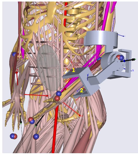
I have the model shown in the attached image. The exoskeleton is attached to the human using AnyKinEq in this model for IK (i.e Exo is driven by the human motion, which is based on some mocap data). For ID, I have used 6DOF forces, and the model works fine for IK and ID.
I am wondering if it is possible to drive the exoskeleton revolute joint based on the human - exoskeleton interaction forces at point 1 & 2 (marked on the attached image), rather than Exo is just attached to the human arm as it is in my current model.
In other words, my aim is to look at the interaction forces at point 1 & 2, command an assistive torque accordingly to the Exo revolute joint, and transmit that assistive force to the human through point 1 & 2.
Is this possible to do in AnyBody and would I be able to observe any reduction of muscle activations etc. in such model? If so, it's highly appreciated any advices on how to modify my model to accomplish this task?
This is not possible natively in AnyBody. I do understand that this is a very desirable feature for active exoskeletons where you want to be able to detect the intention of the user.
You can do this in two ways I think but they are both going to be a little bit complex:
You can use the python hook to make an external function in Python for the assistive torque.
Alternatively, you can export the interaction force from the simulation, process them to generate the assistive torque, run the simulation again with the assistive torque to calculate the interaction force again and repeat the process till you converge to a solution.
Thank you for your reply. I would like the first approach. I think I would be able to manage sending the two interaction forces to the Python script, calculate the required assistive force and write them back to the AnyBody environment.
However, I am not sure what to do next with that assistive force in AnyBody. If I apply the assistive torque to the hinge joint, it is not going to rotate, right? And if I attach the lower arms of human and Exo kinematically (like using AnyKinEq), then the interaction force calculation does not make sense anymore?
So, is there a way to drive the hinge joint based on the assistive torque we calculated, while being able to calculate interaction forces at point 1 & 2?
You are right, applying any kind of force will not change the motion, unless you are doing an FDK based analysis. AnyBody runs an inverse dynamics analysis, where motion is the input and force is the output. What you would like to do is a forward dynamics analysis... I suppose if you can calculate the assistive torque in an external function, you can also make a function in the external function to drive the motion of the exo hinge joint. But then, it will be up to you provide the function for the motion. Also, you will need to figure out something to do with the original motion that you provided in your simulation. I am not sure how this setup will play out.
If you attach the lower arms of the exo and human with AnyKinEq, I assume you have the reaction forces on. This way you have 6 dof reaction forces at the lower arm interface, as you mentioned in the first post. I am wondering that your exoskeleton has 7dof and then it should need another reaction force to keep the system in balance. Where is this 7th reaction force? You would see the effects of the assistive torque on the interaction force at the lower arm, but in theory, also at the upper arm, if you have modelled it. You can consider different ways to setup the reaction forces...something like three linear reactions at each interface and then the seventh reaction at another degree of freedom.
Thank you for the clarification. Now I understand that Exo arm can not be rotated by a assistive torque given to the hinge joint under normal circumstances, and the underling reason. I appreciate your suggestion to create a function for the Exo motion according to the calculated assistive force. However, before attempting that, I would like to know if there is any other way to create motion from force, since that is required for one of the things that we are trying to validate using AnyBody.
You mentioned FDK in the your answer. Is there a way to use FDK in this regard?
About the model attachments, I have constrained 3 DOF (2 upper arm, 1 lower arm) using AnyKinEq. Another 4 DOF at the hinge joint using AnyCylindricalJoint. All the reaction forces are off for these 7 DOF constraints. Then for ID, I have added 2 6DOF forces at the lower arm and 1 6DOF force at the upper arm. The model runs, however, I am not 100% sure if my attachments are right! Please let me know if you notice any issues with this setup.
You can read more about FDK in this tutorial and this wiki page. Essentially, FDK can simulate motion due to elastic stiffness while considering a static equilibrium. I am wondering if that will be sufficient for your purpose. To implement FDK, you would need to change the hinge joint of the exoskeleton to a rigid joint and switch the constraint type for rotation to force dependent. Then, you would also need to provide some stiffness value for the rotational DOF
Overall, I am not entirely sure how the model will play out because you are really pushing towards forward dynamics, but I am curious (and hopeful) to know if you can get some good results with this model
I suppose the kinematics are going to be ok. But for ID, you have got 18 reaction forces. I am sure this will create problems. You should also be getting a warning at model load about redundant reactions. Quite simply, the solver has too much freedom. You may see abrupt jumps in the interface force where the solver randomly switches from one reaction to another since they are supporting the same DOF. You may also see equal and opposite forces that cancel out. It's hard to trust the interaction force in this case.
You would be better off with using contact elements.
Thanks again for the details. I am also curious to know if FDK can be used in cases where we need forward dynamics. I read the FDK tutorials and then the approach you had suggested seems to be straightforward. I started the process by searching for an sample code for creating a rigid joint with constraints and a rotational DOF defined. I could not find the rigid joint among the joint types listed here. I would highly appreciate if if you could guide me with a code snippet or a place to look in this regard, if possible.
And you are right about the interface forces. I can observe abrupt jumps as expected.
What are the contact elements? Again, I could not find details about this topic. Could you please suggest a place to start with contact elements.
Yea, sorry about the rigid joint. It's called AnyStdJoint in AnyBody. So, the code could look something like this:
AnyStdJoint ExoJoint = {
  AnyRefFrame &Ref1 = ...; // ref frame on exo seg 1
  AnyRefFrame &Ref2 = ...; // ref frame on exo seg 2
  Constraints.CType = {Hard,Hard,Hard,ForceDep,Hard,Hard}; // set the correct rotational constraint as
                                                           // forcedep
};
But, of course, you can also keep your original revolute joint and add a driver and make the CType of the driver as ForceDep. This should be easier to implement as it will need fewer changes. Sorry, I didn't think about that yesterday .
For the contact elements, you can start by reading this wiki page. It's essentially the same concept as GRF prediction. You can also find some examples in the AMMR where they are used, like the seated human.
I tested FDK with the code attached (this is a simplified code with just two links connected with a revolute joint) It's possible to create a rotational movement by giving a force input in this code. It makes sense for some extent, for instance, if I apply +5,+10,+15 values for the force input, it creates proportional amount of a clockwise rotation. Also If I apply -5,-10,-15 etc. for the force input, it creates proportional counterclockwise rotations. However, there are few issues that I don't understand. 1) There is a series of massages while the code running - 'Failed to resolve force-dependent kinematics. Too many iterations used (final force error = 1.344865E+01). Continue anyhow..' . 2) If I apply a large force, say 100, the rotation stops after reaching the horizontal level (this happens in both directions) . I highly appreciate if you could have a quick look at my code and point out what's wrong there.
About the contact elements, I was able to apply it for my project by looking at the seated human model. First I applied three contact elements to my Exo-human model (two at the lower arm and one at the upper arm - at the places shown in the image attached to the first post under this topic). I got a ID error. Then I replaced the contact element of the upper arm with a 6DOF force while keeping the two contact elements of the lower arm same. Now the model runs. However, I am not sure how many contact elements should I actually apply? Should it be 7 since my Exo has 7 DOF?
I had a look at your code and what's happening is that your applied torque is being balanced by the moment on the shank due to gravity. You start at the vertical position and then the FDK solver tries to find a position where the resultant of the moment due to gravity and applied torque at the knee joint is 0. This is why you see the proportional movements in either direction depending on the sign of the applied torque. When you apply a torque that's larger than what can be balanced due to gravity (in this model: 0.4m * 4kg * 9.81m/s^2 = 15.696 Nm), then you end up with the segment horizontal as that position gives the maximum moment due to gravity and the lowest error. The final force error is due to the settings of the FDK solver. You can fine-tune these setting according to the needs of your model. Please see the wiki page that I mentioned before and the reference manual.
Contact elements simulate contact force. So, basically, you get 3 linear forces as the outcome from one contact element. Further, the normal force is unidirectional (so maybe you can think of it as 2.5 dof?). So, you would need to think about this differently than using reaction force. As a minimum, I think, you would need 8 contact elements for an interface arranged in 2 rings of 4 contact elements that are spaced out by 90 degrees. Maybe one ring per interface is ok. But it depends on the interface. You can pretty much simulate the shape of your interface and simulate the contact force accordingly.
Instead of using contact elements, you could also consider using 6dof general force at the interface as done in the SitToStand_Exo model. This is similar to adding 6dof reaction force, except that these forces are minimized in the muscle recruitment. Then, you can add 1 set of 6dof general force at each interface.
If I understand correctly, FDK solver attempt to find a equilibrium position when we apply a torque, and therefore, does not always guarantee a proportional motion for a torque input? If so, I think FDK is not going to work in our case. I will consider your previous suggestion to fit a motion function for the assistive torque.
Actually, I was using 6dof general forces before I attempted contact elements. However, since we need to simulate the effect of two pressure sensors at the front and rear side of the arm (in sagittal plane), I added two 6dof general forces for the lower arm interface. Is this wrong? I think this is where you pointed the issue of redundant reactions and random selection of reaction forces by the solver creating abrupt jumps. So, to simulate our task (two pressure sensors at the two sides of a interface), what is the best option? Can we still use 6dof general forces in a different way or should we consider contact elements?
Yes, your understanding about FDK is correct. The idea behind using FDK is to benefit from the elastic structures so that some small displacement can be used to benefit the solver. The solver will always try to minimize the objective function in the end.
I thought you were using the 6dof reaction forces, which are different from the 6dof general force (that is implemented using recruited force) that I mentioned in the previous post. Adding two sets of 6dof general force at the same interface will create a different issue than using 6dof reaction force. Since the 6dof general forces are minimized, you will probably see an even split of the interface force between the 2 sets. This may still not be the right solution. For your model, the best will be to use contact elements.
I added contact elements in my model, and it is highly appreciated if you could help me to clarify the followings.
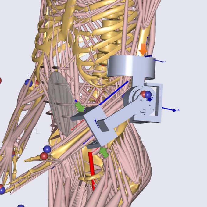
I have two contact elements between the lower arm and the Exo at the places shown in Green color arrows in the attached image 1. In the upper arm, I have a 6DOF General force at the place shown in the Orange color arrow. Model runs for IK, ID. Now, is this setup okay, if I only concerned about the two interaction forces on the lower arm? or should I still use the method you suggested previously (8 contact elements for an interface arranged in 2 rings of 4 contact elements that are spaced out by 90 degrees). Please apologize for asking about this again, but I still don't understand which way is better and why.
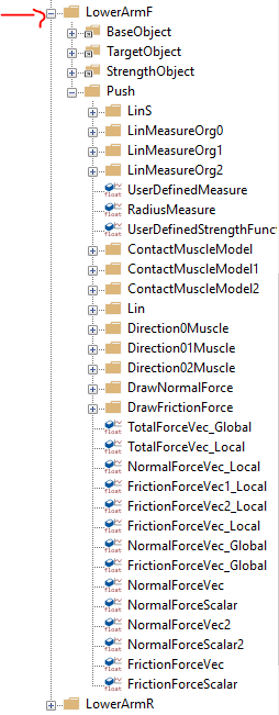
As shown in the attached image 2, there is a series of items when I expand the 'LowerArmF' contact element (the front side interface of the lower arm). Now, if I want the normal force, in the direction of the Green arrow, can I only look at the 'NormalForceScalar' term and ignore all other? If not, please let me know what should I look at.
) It's hard to say which is the best approach when you can arrive at the same result in multiple ways And also, it's not easy for me to foresee all the problems you may face for your model. For your lower interface, having two contact elements at either interface can probably do the job. It would not make sense to add 4 contact elements since you have no contact on the fourth side. But maybe you want to add a third contact element on the lateral side of the forearm if you expect contact over there?