Redundant constraints on my Exo-HumanBody model

Dear seniors,

I am trying to bind my exoskeleton model to the HumanModel, and after researching many posts on forum, I have achieved some results. Here is my work.
Exo_Human.zip (3.8 MB)

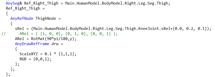
At first, I imported my whole exoskeleton into Anybody, but in the end, I found it a bit difficult. Now my exoskeleton model only retains the both thighs, shanks, and knees. I use AnyCylindricalJoint to connect the exoskeleton kneejoints with the human model kneejoints. Nodes were created on the thighs and shanks of Exo-model and HumanModel, and constraints were implemented using AnyKinEq: the x-axis and z-axis were constrained at the thighs, and the x-axis was constrained at the shanks. Perhaps due to the lack of strict correspondence between the thigh and shank nodes on the exoskeleton and human model, the position of the exoskeleton in the completed kinematic analysis model may be slightly tilted.
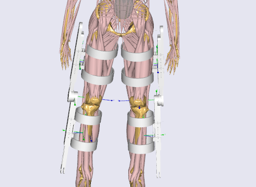
kinematics completed
My thigh and shank nodes are determined based on the corresponding kneejoint node position coordinates, but postures of their kneejoints are different, that should be the reason why the thigh and shank nodes cannot be strictly matched. I don't know if my understanding is correct.


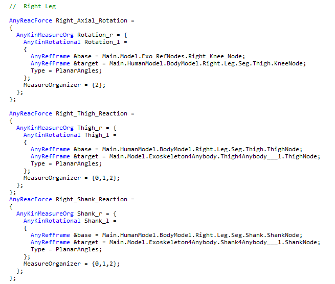
The trouble is with my inverse dynamics analysis. Based on what I have seen in other posts, the added constraints need to be balanced by adding reactions. My single leg has a thigh and a shank, introducing 12 degrees of freedom. In the kinematic section above, I added additional 7 constraints for each leg, so theoretically, I should add 7 additional reactions. I added 7 reactions using AnyReacForce for single leg and set the Constraints.Reaction.Type of AnyCylindricalJoint to {Off, Off, Off, Off}.

Unfortunately, after running the inverse dynamics analysis, it showed redundant constraints and displayed "Muscle recruitment solver : solver aborted due to singular KKT matrix
".

This is beyond my ability, and I hope someone can help me solve this problem :smiling_face_with_tear:.

Best Regards
Meng

1 Like

Hi Meng,

Welcome to the AnyScript Forum!

This looks like a really nice model!

I am not sure I understand you correctly, so I will just try to explain the basics:
Your exoskeleton has 2 segments and that means it has 12 degrees of freedom (dof). I suppose there is a revolute joint between these two segments and that adds 5 constraints. In the kinematics, you add a cylindrical joint (4 constraints) and three additional constraints between the thighs and shanks. So here, it looks good, that you have 12 constraints for the 12 dof.

In the inverse dynamics, you still have the 5 reactions from the exo knee joint, and then you add 7 reactions so that your total comes to 12 reactions. This is also good. You switched off the reactions at the cylindrical joint, so you need to add 7 reactions. I suppose you want to add these reactions at the connecting point on the thigh and shank?

I think the problem is that you have added 3 rotational reactions at the thigh and 3 rotational reactions at the shank. This is leading to the warning of redundant reactions since practically you have added reactions twice in the same 3 rotational dofs because there are the reactions from the revolute joint as well between the exo thigh and shank. So, you should try different combination, like some linear reactions and some rotational reactions. Here is an example of what should work: 3 linear reactions at thigh, 3 linear reactions at shank, and 1 reaction along the long axis of the thigh (or shank).

I hope this helps.

Best reagrds,
Dave

Hi Dave,

Thank you very much for your help!

First of all, I apologize for my carelessness. When I opened my file again, I found that I made a mistake when adding a reaction on left thigh of Exo: I placed the name of shank in the position of
thigh :sweat_smile:. As you pointed out, I added repeated reactions. After correcting this error, I attempted to run inverse dynamics analysis, but it still showed redundant reactions. That indicated that there were sindeed errors in my code, rather than just letting others waste time on my carelessness.

I followed your suggestion and modified the added reaction. The inverse dynamics analysis successfully completed! :yum:

I noticed that in the AMMR, there is a folder named 'Plug in gaitSimple', which contains a file called 'FullBody. main'. I added my exoskeleton to the simple gait model and added the same constraints and reactions as before. I ran the analysis on this model without adding external torque, and the entire process went very smoothly. It's not an exaggeration to say that every successful operation of the dynamics fills my heart with excitement.My next step is to study applying external torque to Exo joints in order to reduce muscle activity in gait. I hope my research approach is correct. Sincere thanks again for your help!

Best regards,
Meng

Hi Meng,

I am happy to hear your model is working!

It's really nice that you are also able to add your exo model to the mocap model without hiccups. I will suggest you use the mocap model with ground reaction force prediction. This is because with the standard Plug-in-GaitSimple model, you have the GRF recorded with force plates. This recorded GRF will be applied to your model. However, when you add an exoskeleton model, I expect the GRF to change. But you will only see the recorded GRF in your trial and this may not give you a complete picture. This is why I suggest you use the GRF prediction class template so you are able to see the changes in GRF depending on the exo model.

Best regards,
Dave

Hi Dave,

Thank you for providing guidance on my work!

After reviewing your suggestions, I researched the Fullbody_GRFPrediction model(I will abbreviate it as GRF model). Due to the shared Input folder between GRFPrediction model and Fullbody model, and my exoskeleton as well as binding and constraint related code being stored in this folder, when I opened the file of GRF model, my exoskeleton also appeared in the view. After running the analysis, I found that the results were much beyond my expectations. After repeatedly comparing the inverse dynamics analysis results of the Fullbody model and the GRF model, I found some problems. I would like to ask you the following questions.

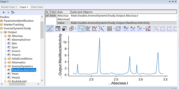
  1. MuscleActivity, I believe it is a value between 0 and 1. In the Fullbody model, regardless of whether my exoskeleton is added or not, the MaxMuscleActivity is between 0 and 1. However, for the GRF model, even without making any changes to the model (without adding exoskeleton), the MaxMuscleActivity far exceeds 1. Is this normal? In the face of this situation, I am not sure if I should use the GRF model for simulation experiments.
    image

  2. To apply knee joint assisted torque in Fullbody model, my approach is to check the JointMomentMeasure of KneeFlexion after wearing the exoskeleton (without applying auxiliary torque), export the data, fit the curve using sine functions, and apply it as a function of time to KneeFlexion. Please notice that there is no negative sign before my function. I believe that applying torque in this way can have an assisted effect rather than increasing the burden on the knees, and this approach does indeed reduce the MuscleActivity of many muscles. Do you think my approach is correct?

AnyForce Knee = {
    AnyKinMeasure &knee = Main.HumanModel.BodyModel.Interface.Right.KneeFlexion;
    F = {18.73*sin(10.02*t-0.0564)+16.87*sin(0.7468*t-1.484)+ 7.756*sin(7.484*t-3.084)+ 4.852*sin(14.72*t-2.199)+ 3.288*sin(20.46*t+1.5)+ 1.925*sin(18.38*t-4.61)+ 2.891*sin(27.35*t+0.5108)+ 9.702*sin(1.639*t+5.65)};
    //    F = {0 };
    viewForce = {
      Visible = On;
      ScaleToView = Off;
      AppliedForceColor = {1, 0.1, 0.1}; 
      ForceScale = 0.005;
    }; 

Best regards,
Meng

Dear Meng,

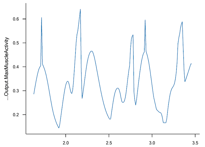
I have ran a default model of Plug-in-gait-Simple/FUllBody_GFRPrediction.main and I do not see the high peaks that you see without the EXO. Here is the result of the MaxMuscleActivity, which is between 0 and 1.

I suggest that:

  1. Investigate where in your trial the picks of MaxMuscleActivity happens.
  2. Find which muscle is actually the one with MaxMuscleActivity.

And try it without the EXO first and then add the EXO and see the differences.
The big peaks in the muscle activity also can happen because of the data. Since you see the high peaks with and without the EXO, then you probably made the EXO model correctly :slight_smile: And maybe you should look at the data more closely.

You can use AnyReacForce on different joints and connections to investigate where you need to have high forces or moments, and susequently find where is the problem in the model, which cause big forces in the muscles :slight_smile:

About your second question, it is a simple and maybe a good way of simulating the EXO without the weights of the EXO and interface connections.

Best regards,
Hamed

Hi Hamed,

Thank you for your suggestion. I checked the CorrectedActivity of most of the muscles in the legs and found that the MaxMuscleActivity does not seem to occur in the legs. Analyzing the default model using Hill muscles, some leg muscles have a peak activity level exceeding 1, but it has not yet reached a level exceeding 10.

The most critical issue is that I analyzed a default file that has not been modified at all, but still encountered such an issue.

I want to know if this issue may be related to the versions of AnyBody and AMMR. I am using versions 7.4 of Anybody and 2.4.3 of AMMR. May I ask which version of AnyBody and AMMR are you using?

Best regards,
Meng

Hi Meng,

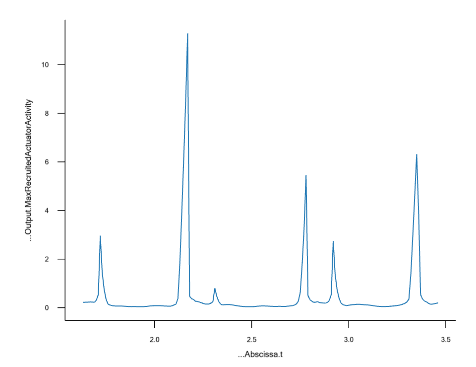
I understand the reason for the confusion. When you plot the Max Muscle Activity in AMS 7.4, it also includes the general muscles that are used for simulating GRF and the weak residual forces. The overload actually happens in the weak residual general muscles and not in the physiological muscles. Of course, it is quite confusing for some users to think that a physiological muscle is with activity over 10, but you don't see any muscle being overloaded in the model view

Therefore, in AMS 8.0, we have introduced AnyRecruitedActuator, that is used to simulate recruited force such as GRF and weak residuals. Functionally, recruited actuators work exactly like general muscles, but they can be organized differently and this allows the model to make a distinction between recruited forces simulated by muscles and recruited forces simulated by recruited actuators. This is also useful when you want to work with metabolic and fatigue models. Then you can apply them to muscles only and not recruited actuators. Please see below the plot for MaxRecruitedActuatorActivity, which is similar to MaxMuscleActivity that you saw.

Best regards,
Dave

Dear senior colleagues,

As a novice in this field, after studying some posts on the forum, especially with the help of your posts, I attempted to model a simple 2-segment exoskeleton with twelve degrees of freedom. Following your modeling approach, I added a rotating joint with five constraints between the two segments, and then added an AnyCylindricalJoint (with four constraints) between the legs and the exoskeleton. Utilizing three additional constraints with AnyKinEq, the model now has 12 degrees of freedom and 12 constraints, which should result in deterministic kinematics. After running the kinematic analysis, the model successfully simulates motion. I am truly grateful for your assistance!

Here, I have a few doubts and would like to seek guidance from the experienced members of the forum. I hope to receive your help. Thank you.

  1. I would like to inquire about how you define the position of the exoskeleton model in SolidWorks. How is it that when you import the exoskeleton into AnyBody, the position aligns so well with the human body without requiring major adjustments to the EXO model's r0 and Axes0 to match the position of the human body? Did you consider the relevant dimensions and initial positions of the human body model when initially assembling the exoskeleton in SolidWorks?

  2. Regarding adjusting the exoskeleton model's r0 and Axes0 to match the position of the human body in AnyBody, how can I move the entire exoskeleton model as a whole to match the position of the human body? In my case, the exoskeleton consists of two ends. My understanding is that I need to separately change the r0 and Axes0 within the AnySeg for each end, which seems relatively straightforward. However, there is an issue here. By individually adjusting the r0 and Axes0 of each segment in the exoskeleton, when loading the model into AnyBody, the system does not consider these constraints. At that moment, the system will place them in space according to their defined position attributes. As a result, the exoskeleton model is separated. Only after running the kinematic analysis do the constraints come into effect, and the exoskeleton becomes a whole. If my exoskeleton consists of many rigid bodies, adjusting each AnySeg's r0 and Axes0 to match the human body model becomes extremely complex. Moreover, after these adjustments, when loading the model into AnyBody, the exoskeleton segments may appear as a large and messy pile, resulting in poor visual effects and hindering the creation of constraints to link them with the human body model. If the positioning of the segments during definition is chaotic compared to their final positions, the system may not resolve the constraint conditions correctly, possibly leading to the failure of kinematic analysis. Is there a method to move the entire exoskeleton model as a whole to match the position of the human body, rather than moving the position of the human body to match the exoskeleton?

Best regards,

Ark

Hi Ark,

I also encountered these problems.

  1. Based on my experience using AnyBody, the x,y,z axes of model inherit the properties of itself in SOLIDWORKS. The origin position in the assembly corresponds to (0, 0, 0) in AnyBody. If you don't want to adjust model's r0 and Axes0 in AnyBody, you need to plan the pose of Exo in advance in SOLIDWORKS. The relevant dimensions and initial positions of the human body model need to be considered in advance when assembling the exoskeleton.

  2. Based on my understanding of AnyBody, the various constraints you have set will not work before running the analysis. After running the analysis, AnyBody will start calculating and solving based on constraints. At this point, the various components in your Exo will be connected under constraints and operate like a whole. The initial position you set is only to help the software solve faster. I think if you set enough constraints and are tight enough, even if you place the two components that should have been connected in Exo at the South Pole and North Pole, and run the analysis, they can still be finally connected and work together :grinning:.It seems impossible to move Exo as a whole in AnyBody, perhaps? :thinking: This requires more professional personnel to answer.

Best regards,
Meng

Hi Ark,

I think Meng answered your questions mostly. I will just add my two cents:

  1. This is a real issue and is something we have heard on the forum before. We have noted this and will try to do something about it. It's just hard to say when, amongst all the other activities that are planned.

  2. Meng's explanation about r0 and Axes0 is correct. At load-time, only r0 and Axes0 are used. It's only when the analysis is run that the constraints are solved. There is just one extra point that I can add on how to move the whole exo together when you set r0 and Axes0. You should set r0 and Axes0 of one segment, and the rest of the segments should make use of the r0 and Axes0 values of the first segment, plus translational and rotational offset. Basically, set r0 and Axes0 of the remaining segments as a function of the r0 and Axes0 of the root segment. You can find some inspiration if you look at the code for the human model. This is how all the human model is moved together at load-time when you change the pelvis position and rotation, or change some joint angles through Mannequin.any file. :wink:

Best regards,
Dave

Dear Meng and Dave,

Your insights and guidance have resolved my doubts, and I believe I now understand how to properly adjust the EXO model to match human positions. Thank you very much for your assistance!

Best regards,
Ark

Dear Dave, as well as Meng and Ark, and other experienced members,

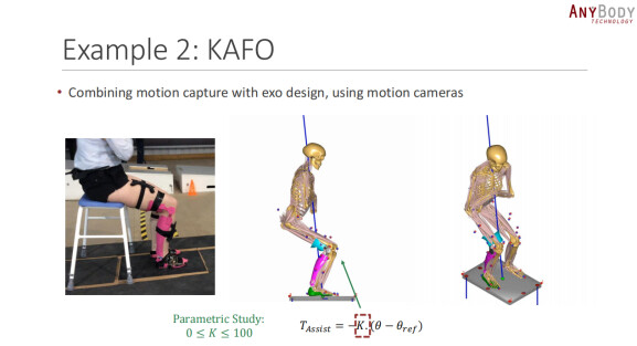
As a student who has recently started learning about this field, I watched the "AnyBody Webcast - 2017.05.30 - Assistive Devices - Simulating Physiological Performance" (https://www.youtube.com/watch?v=PouFpj30vA8) and became interested in Case 2 (KAFO) (as shown in Figure 1). After some time of studying, particularly with the help of the posts from you and other seniors, I began attempting to model a simple 3-segment exoskeleton with 18 degrees of freedom, following your modeling methods. However, I encountered some issues and have some questions. I am seeking guidance from the experienced members of the forum and hope to receive your help. Thank you!

  1. Regarding the "AnyBody Webcast - 2017.05.30 - Assistive Devices - Simulating Physiological Performance," specifically Case 2 (KAFO), I would like to ask if there is any source code available from AnyBody for reference, or if any research papers on this study have been published. I would greatly appreciate your help with this! (My email is yingzz9464@yeah.net)

  2. Concerning kinematics, I have some questions about connecting the exoskeleton to the human model. How should constraints be correctly added to achieve the correct connection between the exoskeleton and the human body?

    • The human model is the Squat from the model library. The exoskeleton consists of three rigid bodies: the thigh, shank, and foot, with a total of 18 degrees of freedom. The thigh and shank are constrained using an AnyRevolute Joint (exoskeleton knee joint) to limit 5 degrees of freedom, and similarly, the shank and foot are constrained using an AnyRevolute Joint (exoskeleton ankle joint) to limit 5 degrees of freedom. This leaves 8 degrees of freedom for the exoskeleton, requiring 8 constraints between the human and the exoskeleton. Therefore:
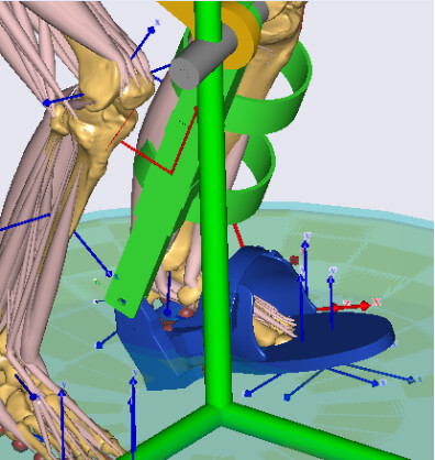
      ①, I added 4 constraints using an AnyCylindricalJoint between the human knee and the exoskeleton knee joint, and added the remaining 4 constraints using AnyKinEq: constraining the x and z axis translation at the thigh connection, constraining the x axis translation at the shank connection, and constraining the y axis translation at the foot connection, referencing a point on the exoskeleton foot plane with the global reference frame (Main.Model.Environment.GlobalRef). The model runs successfully in Kinematics, but it has a problem (as shown in Figure 2): the exoskeleton foot is tilted and not parallel to the ground or the human foot.
      ②, similar to method ①, I added 4 constraints using an AnyCylindricalJoint between the human knee and the exoskeleton knee joint. Then, added the remaining 4 constraints using AnyKinEq: reducing one constraint at the thigh connection (only constraining the z axis translation), keeping the constraint at the shank connection (x axis translation), and adding one more node coordinate at the foot connection to constrain two y axis translations, referencing two points on the exoskeleton foot plane with the global reference frame (Main.Model.Environment.GlobalRef).
      The model fails to run, showing an error: ERROR(OBJ.MCH.KIN3): Squat.main.any(46): Study.InitialConditions: Kinematic analysis failed in time step 0: Failed to solve position constraints.
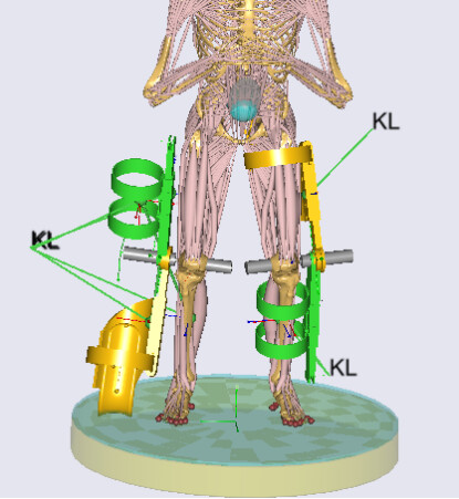
      ③, I added an exoskeleton to the other leg, temporarily adding only two segments (thigh and shank, with a total of 12 degrees of freedom, constrained similarly with an AnyRevolute Joint). Using the same method as ①, I added 4 constraints using an AnyCylindricalJoint between the human knee and the exoskeleton knee joint, and added the remaining 3 constraints using AnyKinEq: constraining the x and z axis translation at the thigh connection, and the x axis translation at the shank connection. The initial position of the model is normal, but after running the kinematic simulation, the right leg exoskeleton is inverted while the left leg exoskeleton is normal (as shown in Figure 3). I am very confused about this issue and hope to receive your guidance. Thank you very much!
  3. Regarding inverse dynamic analysis:

    • I understand that 18 reaction forces are needed to balance the 18 constraints. Since the thigh and shank in the exoskeleton model are constrained using AnyRevolute Joint, and similarly for the shank and foot, there are still 10 reactions from the exoskeleton knee and ankle joints. The remaining 8 reactions might come from the connections between the human and the exoskeleton, making a total of 18 reactions. I plan to add reactions using AnyReacForce: 3 linear reactions at the thigh connection, and 3 linear reactions at the shank connection, at the same node positions as in question 2. Each of the knee and ankle joints will have a reaction torque along the axis, making 8 reactions in total. Is this feasible? Additionally, I would like to understand the purpose of adding these reaction forces/torques. Does it imply that there are 8 motors in the exoskeleton assisting the human body? I look forward to your help. Thank you!
    • After applying torque to the EXO, creating contact between the EXO and the human is necessary. The best method seems to be creating conditional contact elements between the human and the exoskeleton. I checked the "Support.any" file in the SeatedHuman model and studied the input conditions of the "ContactSurfaceLinPush.any" file. The AnyRefFrame &BaseObject and AnyRefFrame &TargetObject reference the node coordinates. Are these the nodes used to define the constraints between the exoskeleton and the human in question 2? I am a bit confused and couldn't fully understand it.

Best regards,
Ying

1 Like

Dear senior colleagues,
The following is an attached picture, thank you again, and look forward to receiving help and guidance from your seniors:
Figure 1
image
Figure 2
image
Figure 3
image
Best regards,
Ying

Hi Ying,

Welcome to the AnyScript forum!

We don't have any source code for the KAFO project that we can share publicly. However, I can refer a couple of exoskeleton models on our Github repository that can be helpful for you. The sit to stand exoskeleton and the stair assist exoskeleton.

Regarding your particular case, I believe the problem in the first approach is that you try to use AnyKinEq in the y-axis between GlobalRef and a point on the exo foot plane. The human foot is also on the ground, so I expect the exo foot should be below the ground (or global ref), or if the the exo is on the global ref, then the human foot should be slightly above the ground. So, there are several ways in which you can fix this. One way could be to replace the AnyKinEq with an AnyKinEqSimpleDriver and provide an offset instead of driving it to zero.

The second set of constraints won't work as you have not provided a set of constraints that can drive the exo knee joint. You provide only the z axis at the thigh and not the x axis, so the exo knee joint is indeterminate in the analysis.

In the third set of constraints, I believe, you would need to look at the axis of the exo and human knee joints for the right and left side. The right and left human knee joints have the z axis pointing to the right. You should check if your exo model for the right leg has the appropriate definition of the knee joint axis. If not, it can flip around the model as you see.

Regarding the inverse dynamics analysis, using reaction force can be limiting as you correctly noted that you need to add a limited set of reactions and there are several ways in which you can do this. The purpose of these reactions is to provide an interface between the human and exoskeleton so that the exoskeleton can effectively support and assist the human. Some of the reactions, like at the exo joint, simply provide reaction forces and moments to simulate the mechanical structure of the exo. While some others, like those between the human and exo provide the interface force between the human and exo. I would suggest you use the conditional contact elements instead of reaction force to simulate the human-exo interface force, like you can see in the two examples that I linked above. Then, BaseObject and TargetObject should be two reference nodes where you want to simulate the interface force, so maybe where you strap the exoskeleton to the human. One of them should be on the exo, and the other on the human.

Further, I would suggest you read our wiki page on how to connect an exo to the human.

I hope this helps. I am sorry if I didn't answer all the questions, but I hope it gives you an overall idea. If you still have some questions, please don't hesitate to write again.

Best regards,
Dave