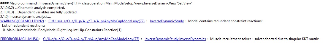
You can see my model attached (New Model\Application\MocapExamples\Plug-in-gait_Simple\ LowerExtremity.main.any). An external band connecting two nodes passes through a segment (that adapts a marker location) in between. However, I get the “solver aborted due to singular KKT matrix” error when I run the inverse dynamics. In the InverseDynamicsStudy description, the model has the same number of d.o.f. and constraints (180).
A KKT error in the inverse dynamic analysis means that there is a degree of freedom in the model which can not be balanced either by a muscle or by a reaction force.
I can be difficult sometime figure out which DOF is causing the problem please see this guide for solving such problems.
Out wiki pages has a generic guide for such problems please see
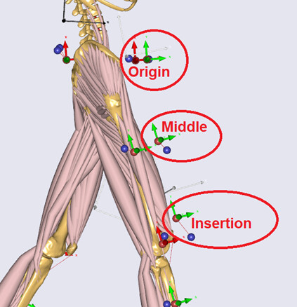
I am trying to model an external band that assists hip flexion and is tracked with 5 markers (1-5). Markers 1 and 5 are fixed to the origin and insertion of the band, so I define them as nodes. However, markers 2-4 are located in the middle of the band.
There are two problems:
Although markers 2-4 are not physically attached to the body, when I define them in Markerprotocol.any, they require a MarkerPlacement as an obligatory member of CreateMarkerDriver. So, I attached them to the closest limb. Is it possible to define a free-floating marker that is not attached to the body?
Consider marker 3, which is attached to the band's middle. The next problem is that to add this marker as a point in space, I add a massless dummy segment. The segment's 3 rotation d.o.fs are fixed with AnyKinEq, and its 3 location d.o.fs are addressed by adapting the marker's location (AnyKinDriverMarker). But when I run the model, the KKT error happens. Is there any problem with this setting?
A marker will always need to be attached to the segment of some kind either a body segment or a artificial segment.
Very likely the KKT error you see relates to the extra segment. Even though the new segment has zero mass it will need to have 6 reactions (3 x forces + 3 x moment) one way or the other.
The AnyKinDriverMarker object does not by default add reactions. So you will need to add some force reactions for the model to work. You could simply enable the reaction in the driver for that maker so a line like below added inside Main would work.
However, after I enabled Reaction.Type for AnyKinDriverMarker; the model still displays a KKT error.
Let me show you a picture, so you can see the problem clearly.
As you can see in this picture, a free-floating marker is placed in the middle of the band, and it should not be attached to the thigh. In my case, MarkerPlacement for this marker is Right.Leg.Seg.Thigh; therefore, the onset of Reaction.Type affects the thigh segment and results in KKT error.
Now, how can I add the middle marker to the model without attaching it to the thigh? This marker is necessary for the model as it helps estimate the band length accurately.
As i understand the model from earlier is that you have a free floating dummy seg, which now should have 3 moment reactions using an AnyKinEq and three force reactions through the modified marker driver. This should in principle be enough for the model to avoid problems.
I think the issue is that the reaction on the marker driver I suggested applies only to the markertracking model not to the inv. dyn. model. These drivers are not part of the inverse dyn model it runs on the extracted angles. So you will need to add a linear measure from the dummy seg to the world and a reaction force to it.
Alternatively to be using the band markers directly as marker drivers you could use them to calculate the lengths of the band directly. In ModelTress you can find all the markers in the location "Main.ModelSetup.C3DFileData.Points.Markers.XXX"
Each of these markers has an interpolation function (Main.ModelSetup.C3DFileData.Points.Markers.XXX.PosInterpol) which contains their pos. So using these interpolation functions you could easily estimate the length of the band directly.
Eg.