I am a novice in AMS and now trying to simulate motions recorded by Xsens (bvh file) using AnyMoCap framework.
The pre-cooked framework worked well when I simulated motions without load, but when I want to simulate some motions with external load (e.g., the subject is carrying a 10 kg box during bending motion), it’s difficult for me to write some codes and add them in the right place to conduct the analysis.
I searched some relevant examples (e.g., standlifting examples) in AMMR but still can not understand, especially the complex connection between human model and environment model. I found some similar problems when I was writing this post but didn’t get clear answers from previous replies.
So how can I achieve it? Or do you have some good examples or materials to share with our community members about this kind of research purposes?
Great thanks for your efforts and reply in advance!
You can define an AnyForce3D object acting on, say, a node on the hand segment. You can define a force acting in the coordinate system of the node, or in global. In case of the box it should be a global force equal to m*g. You may want to split it in half and use 2 AnyForce3D objects for both hands. This is the easiest way to define an external load.
It is also possible to add an actual box object. But it becomes a little more complex. An example is shown in AMMR/Application/Examples/StandingLift. Please see how the object is defined in the Environment.any and how the connection to the human is defined in the JointsAndDrivers.any. You are welcome to copy this code.
Thanks for your kind reply and suggestion first. I tried the first method you mentioned here (AnyForce3D) and meet two questions. Hope to get your further help.
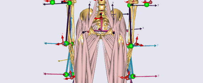
I checked the AnyMoCap framework's body model. It seems that it had symmetric nodes on the hand segment while not drawing it (in the HandSeg.any file). So I drew it out using one line code (AnyRefNode HandNode = { sRel = ..Scale(..Data.Hand_pos *..Mirror);
AnyDrawRefFrame Drwnode = {};} and after I load it I can see the nodes there as below.
But when I used the AnyForce3D to add the external load. I don't know where I should put the codes in the framework and if the codes are right or not. But after I tried, I couldn't load the model and always met the error of "Unresolved object", I guess it's because that I am not familiar with the data structure in AMS. Could you please help me check it and guide me go through this process?
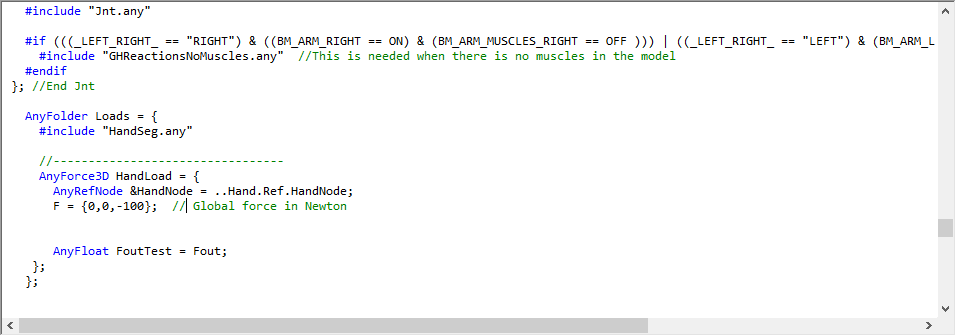
I put the codes in the ShoulderArmModel.root.any file like this.
First of all, please do not touch the internal body model - try making all changes in your application, not inside the human body model. Unfortunately we will not be able to help you once you modified the body model. Please add code externally.
You can always access those node through a slightly longer relative path. Something like:
You could also reuse the PalmJoint node to apply the force. Sometimes you can browse available nodes in the ModelTree and visualize them by, say, pressing F11 (if you use one of the newer AnyBody versions).
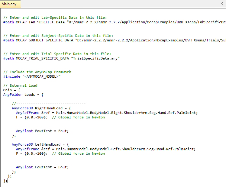
Please try using these nodes and your AnyForce3D objects somewhere in the Main file or an included file:
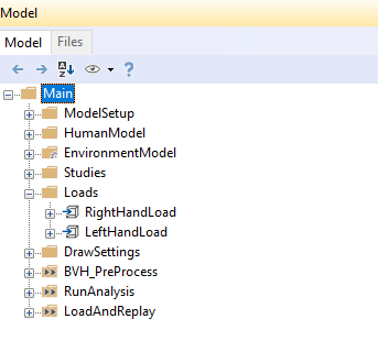
Sorry to bother you again here. I followed your guidance to include the application codes of adding external load at two hands in the main file (showed as below). The model can be loaded and I can see the loads in the model tree.
However, after I checked the result of the analysis, I found that the results for with load condition and without load condition are totally same, which means that the loads here are not included in the inverse dynamics. I guess that I made some mistakes in writing the codes or putting them in the right place. Could you please help me with this issue?
You practically answered you question: these loads will not be included into the inverse dynamics study. You need to open Studies.InverseDynamicStudy folder and add them there (or add them to the EnvironmentModel, which would be more logical).
Thanks for your patient explanation Pavel. It really helps me.Now the loads can be included in the inverse dynamics and the results seems to be reasonable. Correspondingly, I think I have the last question about this topic.
How can I make the load to be time-dependent? For example, given a bvh file with 3000 frames, based on the real situation, I only want the load to be there during frame range of 900 - 2400 (totally 1500 frames) while not the whole 3000 frames, how can I achieve this? Did AnyForce3D support this function? (I checked the manual and it seems it didn't mention about this issue.) I really appreciate it if you can give me a simple example.
Great thanks for your patience, help, and guidance.
Thanks for your reply. It gives me a good direction to explore.
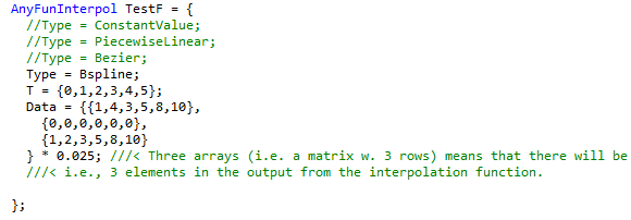
After I check the demo about AnyFunInterPol function (as below), I understood the structure of codes that you provided here. But I still can not understand what’s the meaning for “T” and “Data” inside it, can you explain more about this combining with my real case? My purpose is stated as above: I have a 3000 frames bvh file to analyze, while I want to add the load between 900-2400 frames (take this for example), then how can I write in the T and Data?
I know my question is very basic and I really appreciate your kind reply. Great thanks for your help and patience.
BTW, my external loads are acting on two hands, each with 5 kg (m*g in global coordinates). How to include this in the AnyFunInterpol function? (cause the F here seems changed, not the same as previous’s F = {0,0,-50}, which is kind of easy-to-understand)
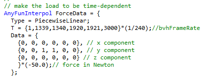
Type = PiecewiseLinear; // BSpline interpolates and you will not get exact values
T = {0, 899, 900, 2400, 2401, 3000} * bvhFrameRate;
Data = {
{0, 0, 0, 0, 0, 0}, // x component
{0, 0, 0, 0, 0, 0}, // y component
{0, 0, 1, 1, 0, 0} // z component
}*(-50.0); // or whatever you want
Great thanks for your help during this process. I think 90% of my problems for now were solved by following your guidance and suggestion.
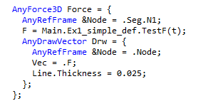
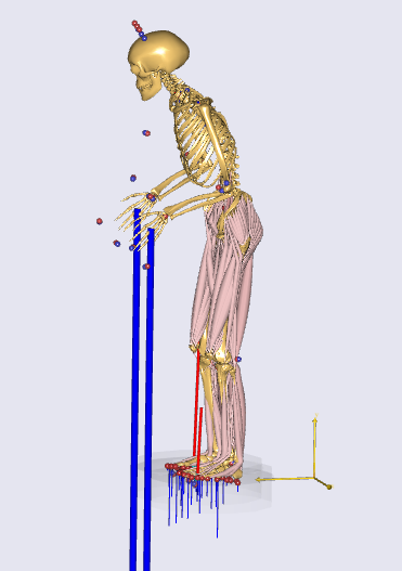
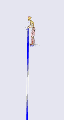
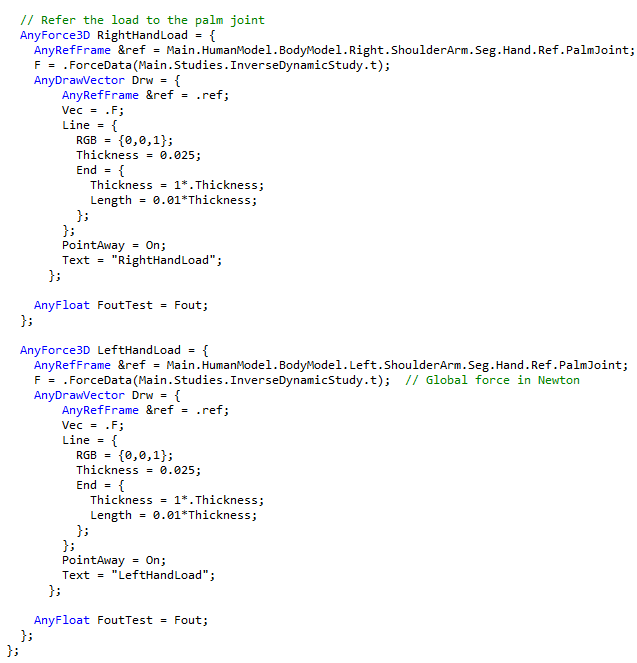
I found one small problem about the codes that you give to me in your last reply: the direction of the force should be put into y component to simulate the m*g, which is showed as below with its visulization, is this right?
I found this problem because of visualization, but you may notice another problem that the load showed here is too long, which is not reasonable and very strange, so I attached my codes for visualization here, could you please help me to check if there are any inappropriate points?
 and after I load it I can see the nodes there as below.