Dear Pavel @pgalibarov
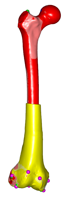
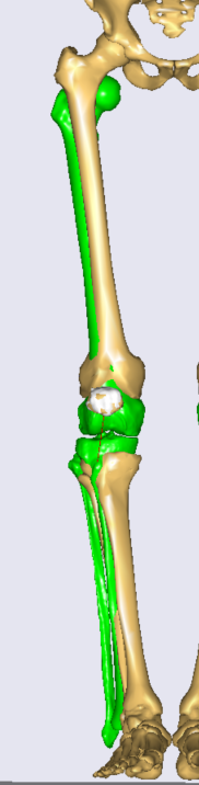
I was wondering how the implementation of such morphing will be. I had a script of a template that morph complete bones. You can directly check the femur part because I started with it and am trying to figure out how to implement the morphing process. The above script (lets call it the template script) works for the model template and produced a nice morphing:
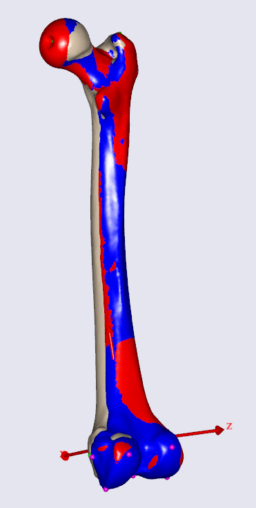
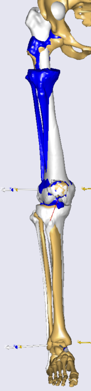
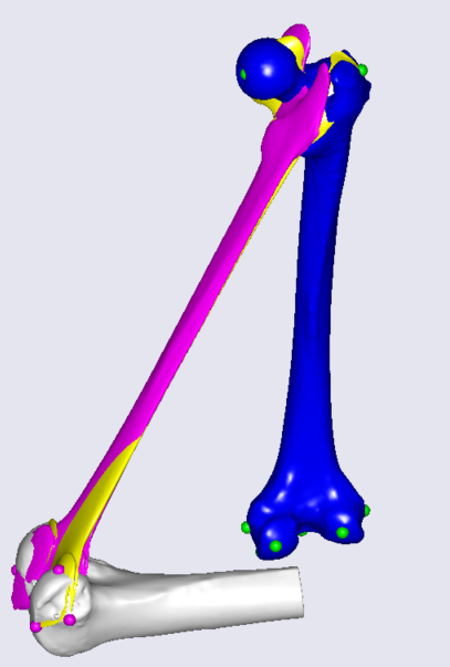
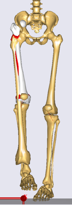
The morphing script (which we have been discussing for the past couple of weeks) resulted in the following transformation:
White =Target femur, blue= source femur, red =affineTransform, and green =RBFTransform.
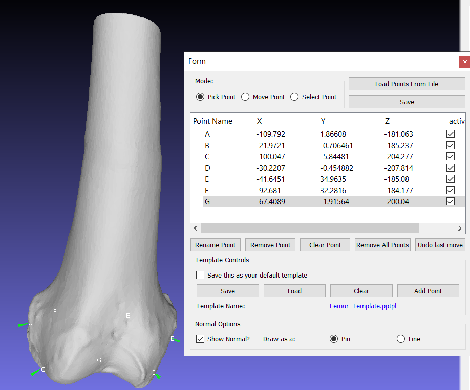
I adjusted the template script to fit my case (distal femur only) following the steps in the tutorial (I might have missed something though!) but I am not quite sure if this how it should be!
AnyFolder Thigh =
{
AnyFunTransform3D &TSeg2ScaleFrame = ...BodyModel.Right.Leg.Seg.Thigh.Scale.T0;
AnyFunTransform3DLin ScaleFunction = {
ScaleMat = {{1,0,0},{0,1,0},{0,0,1}};
Offset = {0,0,0};
PreTransforms = {&.RBFTransform, &.ReverseTransform};
};
AnyFunTransform3DLin2 RegisterDistalLandmarks = {
Points1 =
{ // Landmarks of the distal part of the source bone
{1.4667782, -7.5853477, 40.188442}*0.001, //A
{-1.3872523, -7.2713323, -42.379215}*0.001, //B
{10.828313, -25.093184, 28.204765}*0.001, //C
{-1.2590836, -28.866749, -33.724697}*0.001, //D
{-32.232922, -6.8122239, -26.237719}*0.001, //E
{-24.200073, -7.6667924, 21.916771}*0.001, //F
{8.2392998, -20.800543, -3.7793131}*0.001, //G
{37.3533, 2.90245, 16.3532}*0.001, //H
{30.2449, -6.11178, -14.9986}*0.001 //I
};
Points0 =
{ // Landmarks of the distal part of the target bone
{-2.9408944, -11.066492, 42.313583}*0.001,
{-8.5555677, -8.8688841, -45.743553}*0.001,
{-3.8385994, -35.679928, 34.283401}*0.001,
{-8.4392681, -39.179478, -36.761299}*0.001,
{-39.834358, -12.413182, -27.635822}*0.001,
{-34.514637, -10.991515, 23.638144}*0.001,
{-3.0491183, -30.168438, -1.5138963}*0.001,
{35.6345, -2.0671, 13.8541}*0.001,
{29.8057, -14.0313, -14.7399}*0.001
};
Mode = VTK_LANDMARK_RIGIDBODY;
};
AnyFunTransform3DLin2 AffineTransform =
{
Points0 = .TSeg2ScaleFrame(Points0unscaled);
AnyMatrix Points0unscaled =
{ // landmarks on the distal part of the source bone + two source proximal points (fake points)
{1.4667782, -7.5853477, 40.188442}*0.001,
{-1.3872523, -7.2713323, -42.379215}*0.001,
{10.828313, -25.093184, 28.204765}*0.001,
{-1.2590836, -28.866749, -33.724697}*0.001,
{-32.232922, -6.8122239, -26.237719}*0.001,
{-24.200073, -7.6667924, 21.916771}*0.001,
{8.2392998, -20.800543, -3.7793131}*0.001,
{37.3533, 2.90245, 16.3532}*0.001,
{30.2449, -6.11178, -14.9986}*0.001,
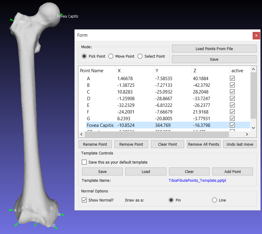
{-10.852421, 364.76874, -16.379839}*0.001, // Fovea capitis
{-19.912188, 362.50815, 45.109447}*0.001 // GTroch
};
Points1 =
{ // landmarks of the registered distal part of the target bone + two source proximal points (fake points)
.RegisterDistalLandmarks({-2.9408944, -11.066492, 42.313583}*0.001), //A
.RegisterDistalLandmarks({-8.5555677, -8.8688841, -45.743553}*0.001), //B
.RegisterDistalLandmarks({-3.8385994, -35.679928, 34.283401}*0.001), //C
.RegisterDistalLandmarks({-8.4392681, -39.179478, -36.761299}*0.001), //D
.RegisterDistalLandmarks({-39.834358, -12.413182, -27.635822}*0.001), //E
.RegisterDistalLandmarks({-34.514637, -10.991515, 23.638144}*0.001), //F
.RegisterDistalLandmarks({-3.0491183, -30.168438, -1.5138963}*0.001), //G
.RegisterDistalLandmarks({35.6345, -2.0671, 13.8541}*0.001), //H
.RegisterDistalLandmarks({29.8057, -14.0313, -14.7399}*0.001), //I
{-10.852421, 364.76874, -16.379839}*0.001, // Fovea capitis
{-19.912188, 362.50815, 45.109447}*0.001 // GTroch
};
Mode = VTK_LANDMARK_AFFINE;
};
AnyFunTransform3DLin2 ReverseTransform = {
Points0 = .AffineTransform.Points1;
Points1 = .AffineTransform.Points0;
Mode = VTK_LANDMARK_RIGIDBODY;
};
AnyFunTransform3DLin2 RegistrationTransform = { // Used to register any target landmark/ nodes
Points0 = .AffineTransform.Points1;
Points1 = Main.Studies.HumanModel.BodyModel.Right.Leg.Seg.Thigh.Scale(.AffineTransform.Points0unscaled);
Mode = VTK_LANDMARK_RIGIDBODY;
};
AnyFunTransform3DRBF RBFTransform=
{
PreTransforms = {&.AffineTransform};
RBFDef.Type = RBF_Triharmonic;
RBFDef.Param = 0.2;
Points0 = .AffineTransform.Points0;
Points1 = .AffineTransform.Points1;
BoundingBox.ScaleXYZ = 5*{1, 1, 1};
BoundingBox.DivisionFactorXYZ = 5*{1, 1, 1};
BoundingBoxOnOff = On;
};
};
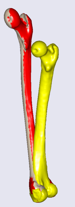
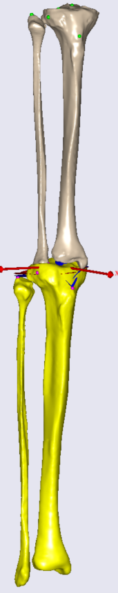
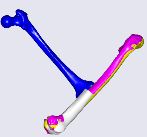
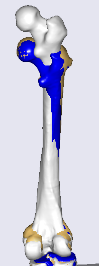
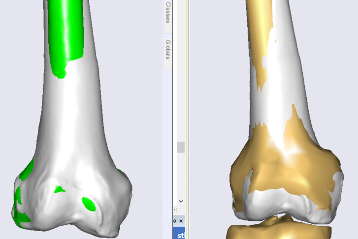
When I run the script for the femur I got something like this:
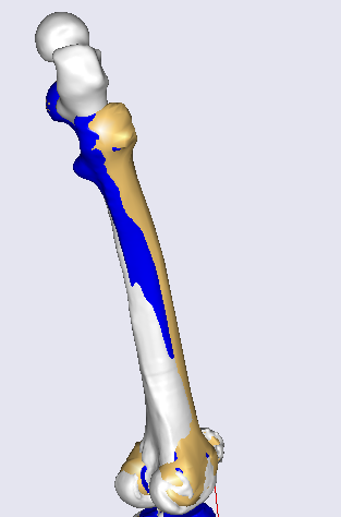
White = Target femur, Blue = Original model source, Yellowish = morphed model bone
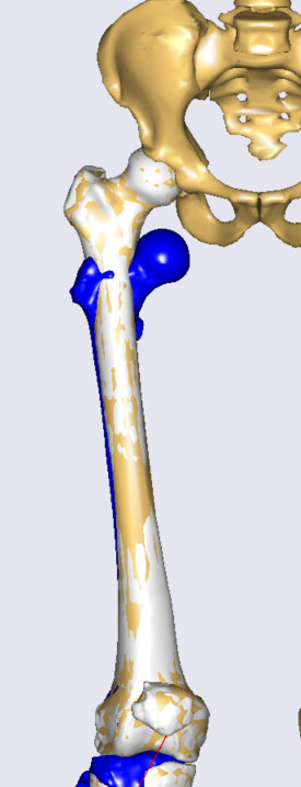
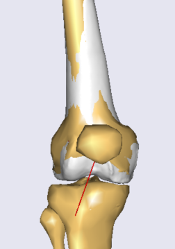
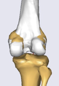
So, comparing the two processes (left = a draft morphing script, right= complete model morphing implementation), I do not feel morphing was successfully implemented in my complete model:
Your advice is appreciated.
Best regards,
Omar