AnyKinVolumeCylMesh - Collapsing Polygons

Hi everyone,

I’m currently working with the Thoracic model (Thoracic.main.any) in AMMR4‑Beta and exploring different ways to modify the existing volume definition.

My goal is to add a custom layer to an AnyKinVolumeCylMesh. The original mesh uses 56 points per layer, but my new layer, Layer_SimplePelvis5.FullEdgeBase, contains only 4 points. To match the expected 56‑point structure, I duplicated each of the 4 points until the layer reached a total of 56 entries. Based on the AnyScript Reference for AnyKinVolumeCylMesh, I expected that this would cause the polygons between Layer_Pelvic4 (56 unique points) and Layer_SimplePelvis5.FullEdgeBase (4 unique points repeated) to collapse into triangles. My custom layer has the required shape of 1×56.


However, when loading the model, I receive the following error message:
"Mesh must contain minimum of 3 entries per row because they are the vertices in a polygon."

My current assumption is that this error occurs because valid polygons cannot be formed between Layer_SimplePelvis5.FullEdgeBase and the following layer, which consists of 56 repetitions of the center node. Since 14 of these nodes lie at exactly the same position, they effectively form a one‑dimensional line toward the center, meaning no surface can be generated. If this is correct, it would mean that it is only allowed to collapse polygons at the top and bottom of the volume (to close it), but not in intermediate layers.

If this assumption is correct, how can the number of points in a non‑closing layer be reduced?

The AnyKinVolume documentation states:
“If you need a mixed set of polygons with different number of vertices, you must fill the ‘Mesh’ matrix with None pointers, because it must be a rectangular matrix in AnyScript.”
Might this be a solution to my problem and how is this implemented in practice?

Thank you very much in advance for any feedback!

Hi Tobias,

I think the issue is the sequence of your points

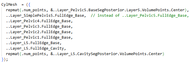
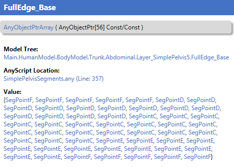
The FullEdge_Base has the sequence : {SegPointF,SegPointF,SegPointF......

This means that the first triangles constructed would be using the points:

..Layer_Pelvic5.BasegSegPosterior.Layer5.VolumePointsCenter, SegPointF,SegPointF

And this is not three individual frames , but only two, because SegPointF are repeated.

If instead your new layer would have the sequence

SegPointC,SegPointD,SegPointE,SegPointF,SegPointC,SegPointD,SegPointE,SegPointF,

Then I think it would have loaded without an error.

As I recall there are no special treatment for the first/last layer allowing these to repeat points. To convince myself this is correct I have made this small sample model :wink:

Main = {
  
  AnyMechStudy Study = {
    Gravity = {0,0,0};
    nStep = 11;
    
    AnyVar H = 4; ///< box height
    AnyVar W = 2; ///< box width

    
    AnyVec3 T = {0,0,0}; // Arbitrary translation
        
    AnyFixedRefFrame  GlobalRef = {
      AnyRefNode n1_0 = { sRel=..T+{..H,..W,0}; viewRefFrame={Visible=On; ScaleXYZ={1,1,1}*0.11;}; };
      AnyRefNode n2_0= { sRel=..T+{..H,  0,0}; viewRefFrame={Visible=On; ScaleXYZ={1,1,1}*0.11;}; };
      AnyRefNode n3_0 = { sRel=..T+{0  ,  0,0}; viewRefFrame={Visible=On; ScaleXYZ={1,1,1}*0.11;}; };
      AnyRefNode n4_0 = { sRel=..T+{0  ,..W,0}; viewRefFrame={Visible=On; ScaleXYZ={1,1,1}*0.11;}; };
      
      AnyRefNode n1_1 = { sRel=..T+{..H,..W,0.25}; viewRefFrame={Visible=On; ScaleXYZ={1,1,1}*0.11;}; };
      AnyRefNode n2_1 = { sRel=..T+{..H,  0,0.25}; viewRefFrame={Visible=On; ScaleXYZ={1,1,1}*0.11;}; };
      AnyRefNode n3_1 = { sRel=..T+{0  ,  0,0.25}; viewRefFrame={Visible=On; ScaleXYZ={1,1,1}*0.11;}; };
      AnyRefNode n4_1 = { sRel=..T+{0  ,..W,0.25}; viewRefFrame={Visible=On; ScaleXYZ={1,1,1}*0.11;}; };

      
      AnyRefNode n1_2 = { sRel=..T+{..H,..W,0.5}; viewRefFrame={Visible=On; ScaleXYZ={1,1,1}*0.11;}; };
      AnyRefNode n2_2 = { sRel=..T+{..H,  0,0.5}; viewRefFrame={Visible=On; ScaleXYZ={1,1,1}*0.11;}; };
      AnyRefNode n3_2 = { sRel=..T+{0  ,  0,0.5}; viewRefFrame={Visible=On; ScaleXYZ={1,1,1}*0.11;}; };
      AnyRefNode n4_2 = { sRel=..T+{0  ,..W,0.5}; viewRefFrame={Visible=On; ScaleXYZ={1,1,1}*0.11;}; };

      
      AnyRefNode n1_3 = { sRel=..T+{..H,..W,0.75}; viewRefFrame={Visible=On; ScaleXYZ={1,1,1}*0.11;}; };
      AnyRefNode n2_3 = { sRel=..T+{..H,  0,0.75}; viewRefFrame={Visible=On; ScaleXYZ={1,1,1}*0.11;}; };
      AnyRefNode n3_3 = { sRel=..T+{0  ,  0,0.75}; viewRefFrame={Visible=On; ScaleXYZ={1,1,1}*0.11;}; };
      AnyRefNode n4_3 = { sRel=..T+{0  ,..W,0.75}; viewRefFrame={Visible=On; ScaleXYZ={1,1,1}*0.11;}; };

      AnyRefNode n1_4 = { sRel=..T+{..H,..W,1}; viewRefFrame={Visible=On; ScaleXYZ={1,1,1}*0.11;}; };
      AnyRefNode n2_4 = { sRel=..T+{..H,  0,1}; viewRefFrame={Visible=On; ScaleXYZ={1,1,1}*0.11;}; };
      AnyRefNode n3_4 = { sRel=..T+{0  ,  0,1}; viewRefFrame={Visible=On; ScaleXYZ={1,1,1}*0.11;}; };
      AnyRefNode n4_4 = { sRel=..T+{0  ,..W,1}; viewRefFrame={Visible=On; ScaleXYZ={1,1,1}*0.11;}; };
      
      AnyRefNode nMid_0 = { sRel= (.n1_0.sRel+.n2_0.sRel+.n3_0.sRel+.n4_0.sRel)/4.0; viewRefFrame={Visible=On; ScaleXYZ={1,1,1}*0.11;}; };
      AnyRefNode nMid_1 = { sRel= (.n1_1.sRel+.n2_1.sRel+.n3_1.sRel+.n4_1.sRel)/4.0; viewRefFrame={Visible=On; ScaleXYZ={1,1,1}*0.11;}; };
      AnyRefNode nMid_2 = { sRel= (.n1_2.sRel+.n2_2.sRel+.n3_2.sRel+.n4_2.sRel)/4.0; viewRefFrame={Visible=On; ScaleXYZ={1,1,1}*0.11;}; };
      AnyRefNode nMid_3 = { sRel= (.n1_3.sRel+.n2_3.sRel+.n3_3.sRel+.n4_3.sRel)/4.0; viewRefFrame={Visible=On; ScaleXYZ={1,1,1}*0.11;}; };
      AnyRefNode nMid_4 = { sRel= (.n1_4.sRel+.n2_4.sRel+.n3_4.sRel+.n4_4.sRel)/4.0; viewRefFrame={Visible=On; ScaleXYZ={1,1,1}*0.11;}; };
      
      viewNodes.Visible = On;
      viewRefFrame.Visible = On;
    };
    
    /// This kin. measure uses the derived class, AnyKinVolumeCylMesh
    /// which enable to enter the box in a simpler format as cylindrical mesh.
    AnyKinVolumeCylMesh VolMeasure_by_cylindrical_mesh = {
      CylMesh = {
        {&.GlobalRef.nMid_4, &.GlobalRef.nMid_4, &.GlobalRef.nMid_4, &.GlobalRef.nMid_4},
        {&.GlobalRef.n1_4, &.GlobalRef.n2_4, &.GlobalRef.n3_4, &.GlobalRef.n4_4},
        {&.GlobalRef.n1_3, &.GlobalRef.n2_3, &.GlobalRef.n3_3, &.GlobalRef.n4_3},
        {&.GlobalRef.nMid_3, &.GlobalRef.nMid_3, &.GlobalRef.nMid_3, &.GlobalRef.nMid_3},
//        {&.GlobalRef.nMid_2, &.GlobalRef.nMid_2, &.GlobalRef.nMid_2, &.GlobalRef.nMid_2},  //not allowed mesh can not be created in meaningful way
        {&.GlobalRef.n1_2, &.GlobalRef.n2_2, &.GlobalRef.n3_2, &.GlobalRef.n4_2},
        {&.GlobalRef.n1_1, &.GlobalRef.n2_1, &.GlobalRef.n3_1, &.GlobalRef.n4_1},
        {&.GlobalRef.nMid_1, &.GlobalRef.nMid_1, &.GlobalRef.nMid_1, &.GlobalRef.nMid_1},
      };
      viewKinMeasure.Visible = On;
    };
   }; // End of Main.Study
};

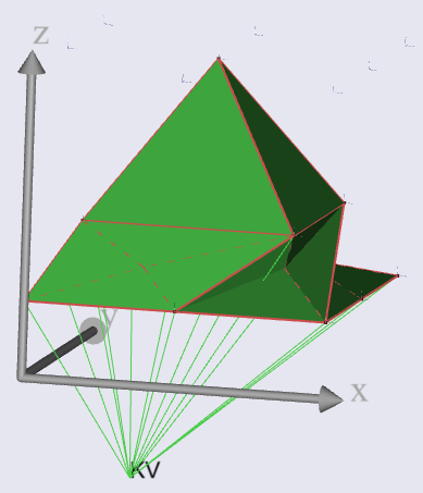
This will create small mesh model,

There is one line out commented if you enable this line it will give the same error as you have seen, but this is also correct, it would try to create triangles based on two points which would not be possible.

Once you get the model to load you can inspect the CylMesh object in the ModelTree it will show the topology of the mesh.

Hope it helps

Best regards
Søren

Hi Søren,
thanks a lot for your reply!

You are right, when I changed my layer sequence to SegPointC,SegPointD,SegPointE,SegPointF,SegPointC,SegPointD,SegPointE,SegPointF,... the model loaded without an error. However, this still doesn't result in the desired volume as it gets weirdly distorted with this.

I adapted the code you kindly provided to match a bit more what I'm actually looking for:

Main = {
  
  AnyMechStudy Study = {
    Gravity = {0,0,0};
    nStep = 11;
    
    AnyVar H = 1; ///< box height (x)
    AnyVar W = 1; ///< box width  (y)
    AnyVar neck = 0.15; // necking for better visualization of middle layer

    AnyVec3 T = {0,0,0}; // Arbitrary translation
        
    AnyFixedRefFrame  GlobalRef = {
            
      AnyRefNode n1_1 = { sRel=..T+{..H,..W,0.25}; viewRefFrame={Visible=On; ScaleXYZ={1,1,1}*0.11;}; };
      AnyRefNode n2_1 = { sRel=..T+{..H,..W/2,0.25}; viewRefFrame={Visible=On; ScaleXYZ={1,1,1}*0.11;}; };
      AnyRefNode n3_1 = { sRel=..T+{..H,  0,0.25}; viewRefFrame={Visible=On; ScaleXYZ={1,1,1}*0.11;}; };
      AnyRefNode n4_1 = { sRel=..T+{..H/2,  0,0.25}; viewRefFrame={Visible=On; ScaleXYZ={1,1,1}*0.11;}; };
      AnyRefNode n5_1 = { sRel=..T+{0  ,  0,0.25}; viewRefFrame={Visible=On; ScaleXYZ={1,1,1}*0.11;}; };
      AnyRefNode n6_1 = { sRel=..T+{0  , ..W/2,0.25}; viewRefFrame={Visible=On; ScaleXYZ={1,1,1}*0.11;}; };
      AnyRefNode n7_1 = { sRel=..T+{0  ,..W,0.25}; viewRefFrame={Visible=On; ScaleXYZ={1,1,1}*0.11;}; };
      AnyRefNode n8_1 = { sRel=..T+{..H/2  ,..W,0.25}; viewRefFrame={Visible=On; ScaleXYZ={1,1,1}*0.11;}; };

      AnyRefNode n1_2 = { sRel=..T+{..H-..neck, ..W-..neck, 0.5}; viewRefFrame={Visible=On; ScaleXYZ={1,1,1}*0.11;}; };
      AnyRefNode n2_2 = { sRel=..T+{..H-..neck, 0+..neck,   0.5}; viewRefFrame={Visible=On; ScaleXYZ={1,1,1}*0.11;}; };
      AnyRefNode n3_2 = { sRel=..T+{0+..neck,   0+..neck,   0.5}; viewRefFrame={Visible=On; ScaleXYZ={1,1,1}*0.11;}; };
      AnyRefNode n4_2 = { sRel=..T+{0+..neck,   ..W-..neck, 0.5}; viewRefFrame={Visible=On; ScaleXYZ={1,1,1}*0.11;}; };

      AnyRefNode n1_4 = { sRel=..T+{..H,..W,1}; viewRefFrame={Visible=On; ScaleXYZ={1,1,1}*0.11;}; };
      AnyRefNode n2_4 = { sRel=..T+{..H,..W/2,1}; viewRefFrame={Visible=On; ScaleXYZ={1,1,1}*0.11;}; };
      AnyRefNode n3_4 = { sRel=..T+{..H,  0,1}; viewRefFrame={Visible=On; ScaleXYZ={1,1,1}*0.11;}; };
      AnyRefNode n4_4 = { sRel=..T+{..H/2,  0,1}; viewRefFrame={Visible=On; ScaleXYZ={1,1,1}*0.11;}; };
      AnyRefNode n5_4 = { sRel=..T+{0  ,  0,1}; viewRefFrame={Visible=On; ScaleXYZ={1,1,1}*0.11;}; };
      AnyRefNode n6_4 = { sRel=..T+{0  , ..W/2,1}; viewRefFrame={Visible=On; ScaleXYZ={1,1,1}*0.11;}; };
      AnyRefNode n7_4 = { sRel=..T+{0  ,..W,1}; viewRefFrame={Visible=On; ScaleXYZ={1,1,1}*0.11;}; };
      AnyRefNode n8_4 = { sRel=..T+{..H/2  ,..W,1}; viewRefFrame={Visible=On; ScaleXYZ={1,1,1}*0.11;}; };
      
      AnyRefNode nMid_1 = { sRel= (.n1_1.sRel+.n3_1.sRel+.n5_1.sRel+.n7_1.sRel)/4.0; viewRefFrame={Visible=On; ScaleXYZ={1,1,1}*0.11;}; };
      AnyRefNode nMid_4 = { sRel= (.n1_4.sRel+.n3_4.sRel+.n5_4.sRel+.n7_4.sRel)/4.0; viewRefFrame={Visible=On; ScaleXYZ={1,1,1}*0.11;}; };
      
      viewNodes.Visible = On;
      viewRefFrame.Visible = On;
    };
    
    /*
    CylMesh consists of:
      8x nMid_4 to close off volume at the top
      layer 1 with 8 individual points
      layer 2 with 4 individual points (each repeated twice)
      layer 3 with 8 individual points
      8x nMid_1 to close off volume at the bottom
    */
    AnyKinVolumeCylMesh VolMeasure_by_cylindrical_mesh = {
      CylMesh = {
        repmat(8, &.GlobalRef.nMid_4),
        {&.GlobalRef.n1_4, &.GlobalRef.n2_4, &.GlobalRef.n3_4, &.GlobalRef.n4_4, &.GlobalRef.n5_4, &.GlobalRef.n6_4, &.GlobalRef.n7_4, &.GlobalRef.n8_4}, // if out-commented, volume can't be created
        {&.GlobalRef.n1_2, &.GlobalRef.n1_2, &.GlobalRef.n2_2, &.GlobalRef.n2_2, &.GlobalRef.n3_2, &.GlobalRef.n3_2, &.GlobalRef.n4_2, &.GlobalRef.n4_2},
        {&.GlobalRef.n1_1, &.GlobalRef.n2_1, &.GlobalRef.n3_1, &.GlobalRef.n4_1, &.GlobalRef.n5_1, &.GlobalRef.n6_1, &.GlobalRef.n7_1, &.GlobalRef.n8_1},
        repmat(8, &.GlobalRef.nMid_1),
      };
      viewKinMeasure.Visible = On;
    };
   }; // End of Main.Study
};

The base-layers consist of 8 distinct points and a mid-layer with only 4 distinct points but each of them is repeated twice so that the layer still consists of 8 points. This mid-layer forces the polygons in the volume first to collapse to triangles and then expand back to quadrilaterals. So, the number of distinct points forming the volume in each layer is 1->8->4->8->1.

However, what I actually want is a volume formed of the following order of distinct points in each layer: 1 -> 8 -> 4 -> 1
This can be done by out-commenting the 2nd line in the CylMesh, which would form some sort of a rectangular pyramid. BUT, as already established, this leads to a loading error because only two individual frames are provided to form a triangle.
When then following your advice and changing the sequence order in the 3rd line in the CylMesh to not having any repeating points, the volume gets distorted.

I think this issue can only be resolved by using None pointers as described in the AnyScript Reference Manual of AnyKinVolume but I do not understand how to implement that and any hint would be greatly appreciated.

Thanks again for any feedback.

Hi Tobias,

Just a quick reply to see how to use the AnyKinMeshVolume please see the object in the reference manual and note that it has also an example model to display the options. It is actually a section of that demo model I used for this model.

The issue if that you will need define to entire mesh topology, it is doable I think but much more work than just defining the rings and then letting cylmesh create the topology of the mesh itself.

I am sorry but can not exactly picture how you would like the mesh to look like. Just a thought you could possibly "fake" the points, so having multiple individual points (differently named) in the same location, then the model would still load even with points being the "same".

Best regards
Søren

Hi Søren,

Thanks again for the reply. I underestimated the complexity of the approach I initially had in mind.

I’ve now adjusted my strategy and solved the problem by adding interpolated points between the segments.

Best regards,
Tobias

1 Like